Party time in Gallery 273 |
QMC Physics Panto Plus!
Although I had thoroughly enjoyed working at the Armstrong factory, my social life certainly improved dramatically once I’d returned to QMC! The problem at Armstrong was that I lived well away from the factory. The production line workers lived close to the factory and went home promptly at the end of the day. The directors all lived in different places. So we scattered at the end of the working day. Hence although we got on well, we had little contact outside work.
At QMC the staff, postgrads, etc, tended to drift off to a local bar for an hour or so after work. In particular a group from Physics used to go to the Senior Common Room bar in the Main building. From there we might then go out for an evening, or to someone’s home. QMC was also a much easier commute for me, so I felt less of an urge to get the trip over with before I could relax. The Physics dept. also had what I came to decide was a key blessing for any organisation – a tea room where people could get together a couple of times a day to have a chat over a cup or tea. We employed a tea lady out of charging for the tea, biscuits, and cheese rolls which were sold. The original tea lady was the formidable Gwen who was prone to make biting comments to anyone who was late for tea or upset her routine. The location of the tea room was called Gallery 273.
|
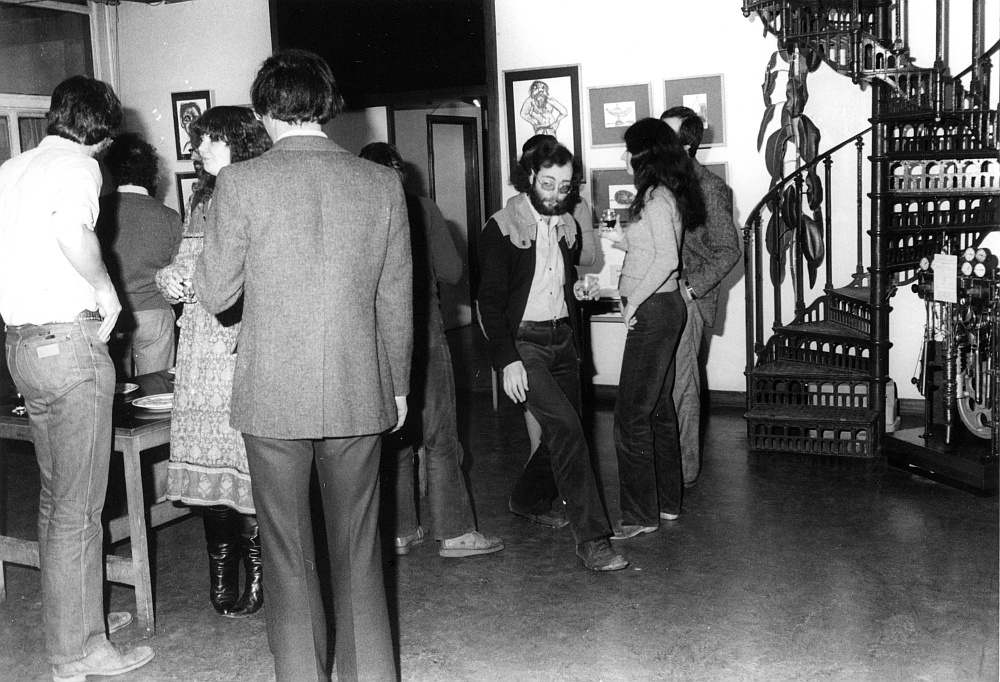
Party time in Gallery 273 |
This was because it was also a place where artists could show their work. In addition to tea, when a new exhibition opened there tended to be a wine and cheese party. The above photo shows one of these events. From left to right you can see: Colin Spratling (computing assistant), Carey (Head of department’s secretary), John Edgington, me, and Rosemary Eve with her spouse, Dave Eve (PhD student), behind her. To the right is the spiral staircase that connected 273 to the corridor of the floor above via a landing just outside the head of department’s office. The staircase was carried over from the old building that the Physics dept. used before the new one was built. The tea room was a good place to chat and get to know people and arrange social events. But it was also an excellent way for people to discuss their work and have ideas emerge from the informal questions or suggestions made by others. This sometimes acted as the spark that caused people researching in quite different areas to help each other, inspire new projects, or formally collaborate. So it was a really useful way to foster academic work.
For me, the social developments manifested in two particular ways. At Armstrong I’d never really had any opportunity to get to know or go out anywhere with any of the women who worked for the company. Everyone just scattered at the end of the day. But the amiable social cohesion of the QMC physics dept gradually lead to my routinely going out to shows, concerts, a restaurant, etc, with various women I knew who also worked at QMC. Maybe this was because I’d grown a beard! In particular, I recall very happily going out often with Chris Adams, Karen, and Chris Robson. Chris Robson was, of course, Ian Robson’s better half, and was at the time actually working in the QMC Chemistry building. But we’d got to know each other well via having to both cope with Ian’s ‘enthusiastic’ approach to life. Karen was the Physics dept’s computing assistant who’d taken over Colin’s job when he left. It quickly became clear that she was much prettier than Colin and enjoyed going out in the evenings. Chris Adams became a mainstay of my life, so I’ll say more about her later on... But overall, in terms of having an enjoyable social life with the fair sex I’d gone from zero to being busy in just a few years. Yes, it probably was the beard hiding my face!
|
|
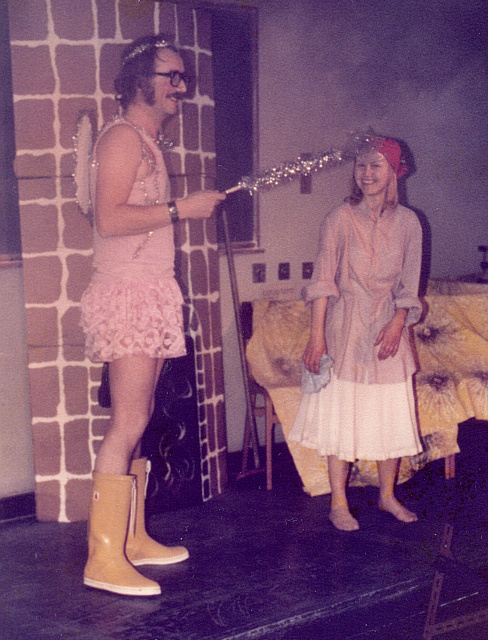
| Prof Guy Wilson as Fairy Godmother Karen as Cinderella |
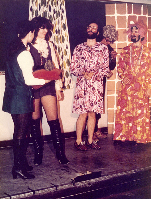
Chris Adams as huntsman, Carey as Prince Charming. Me and John Beckman as Ugly sisters (strategic balloons employed!) |
The second social development was the departmental Pantos. These were inspired – or should I say ‘commanded’? – by Carey Bradd (nee Adams), the head of dept’s secretary. Carey was the no-nonsense ‘Queen Bee’ of the Physics dept. at the time. At some point she decided that she fancied being the star of a panto and that it would be a good idea if staff members could be seen to make themselves look daft by also being in a panto. It was known, that I’d tried to write a bit and had an interest. It was also obvious that I didn’t mind looking daft for a laugh. So I was delegated to help write a panto... which then became an annual event.
During the 1970s I’d written a number of science fiction stories, one of novel-length, the others much shorter. To the unknowing benefit of the reading public, none were ever published. But for a while Leslie Flood took them on as an agent, and sent them to USA magazines like ‘Analog’. This was on the standard basis that he only got paid if the story was sold. So he must have been either hopeful or desperate! Leslie had taken over the Ted Carnell Agency which at the time was the only UK literary agency specialising in Science Fiction. I can’t now recall for certain, but I’m fairly sure Carey knew about this and so took for granted that I could use a typewriter. (No wordprocessors in those far-off days.) So I was duly delegated.
The first pantos were performed in one of the small lecture theatres on the lower ground floor of the Physics building. They were timed to appear after the end of term when undergrads would (mostly) have gone away. The idea was that they were by the staff and departmental workers for the staff and workers. The aim being to be able to laugh at ourselves, have a good time, and simply socialise – and, of course, give Carey her chance to be a star turn!
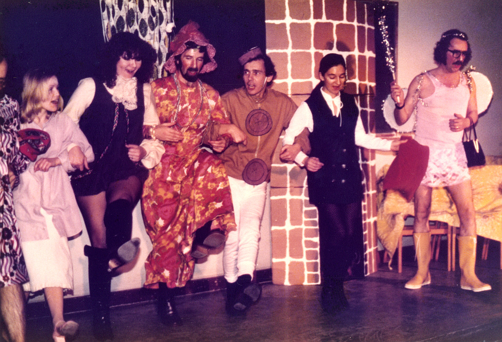
From left to right: Me (thankfully, almost out of view), Karen, Carey, John Beckman, Keith Nicholls (departmental technician), Chris Adams, and the illustrious Prof Wilson again. |
However after the first panto, news got around, and later pantos had to be shifted to the main lecture theatre in the physics building to cope with all the people who wanted to see them. Lots of undergrads would stay around and appear so they could join the audience. They became a social highlight of the year for everyone.
The final QMC panto I was roped into also required me to attempt to act. For the purposes of the plot I had the role of a ‘narrator’ but with a twist. From the start of the play I was sat behind a small table to one side of the stage to present my narrative. However at a key moment there was meant to be a bang and a flash and I had to leap up and expose myself as a fairy godmother. To indicate who I was and reveal my magical status, I had been equipped with a handbag inside which was a 6 volt battery. This was wired via a switch to three large coloured fairy lights – two spherical and the other elongated – stategically placed on the front of my costume. These lights had until this moment been hidden from the audience by the table. At the bang I was to leap up, flash the lights to get attention, and present my magical message. However there was one thing I’d not been told, and something else only one person – Phil Halstead (technician) – knew...
At the vital moment there wasn’t simply a bang and a flash. There was a really colossal BOOOOM! Followed by a loud CRASH! And I didn’t need to move the table or stand to reveal my magical parts because the table flew apart in front of me!
The loud noise was due to Phil having decided that the best way to make the bang was to put a stage thunderflash into a metal dustbin at the back of the main lecture theatre. He also decided to use the ‘large stadium’ size of thunderflash. i.e. a banger designed to make a noise loud enough for the Royal Albert Hall. The result was, erm, rather loud in the lecture theatre. The dustbin lid was also flung up in the air and hit the ceiling with a crash, before falling back to the floor with another crash. As this happened, some explosive bolts in the table also went off, blowing it to pieces in front of me. Something that no-one had mentioned to me was going to happen! At this point everyone was a bit stunned, partly deafened, and could hear ringing noises in their ears. As we all froze we were gradually covered by the dust of many decades which the BOOOOM and bin-lid impact had dislodged from the ceiling. This descended like a sifting of grey flour on audience and cast alike. Sadly, I have no photos of this panto. I do have an old VHS tape, but no longer have a VHS deck, so it remains hidden from modern eyes. The event ‘corpsed’ me in the theatrical sense and all I could do for a while was freeze or laugh, but I finally started to struggle though the next lines and the panto continued. By then I think most people could hear again.
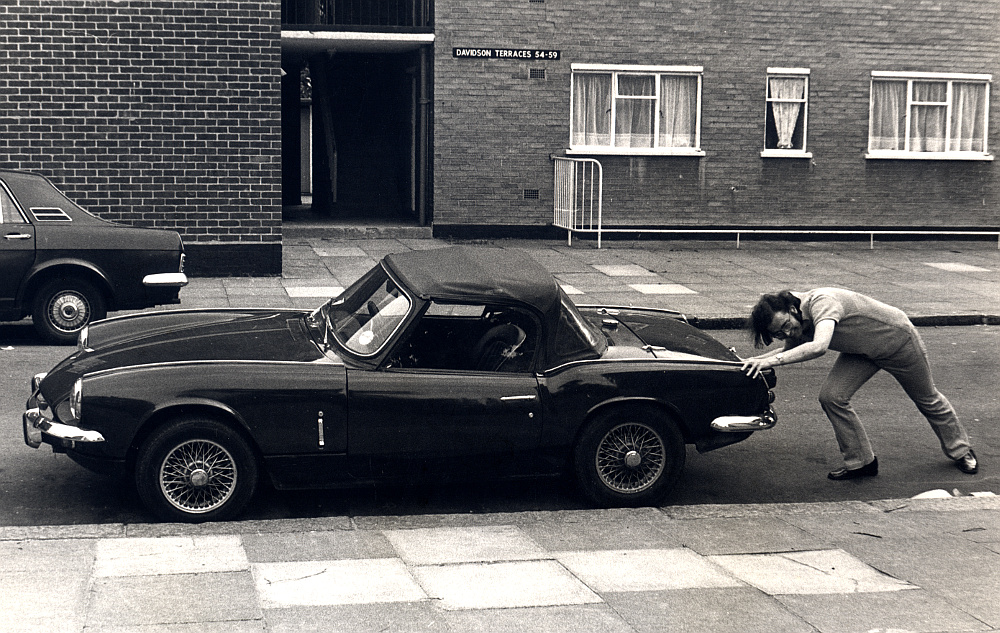
The Pram |
It was during this period that I came as close as I ever did to being physically fit. I once had, briefly, tried owning and driving a car. However I quickly realised that this was, for me, a bad idea. The main reason being that I was an awful driver. Bad eyesight and a tendency for my mind to wander. I concluded that if I went on driving a car I’d end up killing someone – probably me! The car itself was also a nightmare. I’d only been able to afford something cheap and second-hand. So it was in a real state. During the first week I drove it, the car broke down as I was going up the Bow Flyover in rush-hour traffic. It came to a halt three-quarters of the way up and I had to walk back down to a nearby garage to get a tow rescue. It turned out that a previous owner had fitted a new clutch plate, but had with remarkable skill managed to fit it the wrong way around. Amazing that it worked at all. My father dubbed the car, ‘the pram’ because of its soft top. I sold the car later on. It was probably a good thing that the man who bought it was a fireman...
Having got rid of the car I started using a touring bicycle to commute to work, and to get around at night when it was convenient. This was much better in as much that I was out in the open and that helped me to keep aware of what I was doing and what was around me. The main snag was all the vehicle drivers who clearly regarded a bike as either static or a target! I gained the impression that many drivers simply take for granted that as soon as a bicycle is behind their side windows they have ‘overtaken’ it an can immediately pull back over to the left. In the process shoving the bicyclist into parked cars or the pavement.
The other snag was having to breath deeply as I rode along a busy main road, sucking in all the exhaust flumes. So although it gave me lots of exercise, riding a bike was also trying to gas me or get me crushed. I had also started occasionally playing squash. I was utterly hopeless at this because I was far too slow. But a succession of other learners found me a useful sparring partner for a few weeks until they could beat me consistently and move up to better opponents. This didn’t bother me because I simply enjoyed feeling a little bit fitter than I had been.
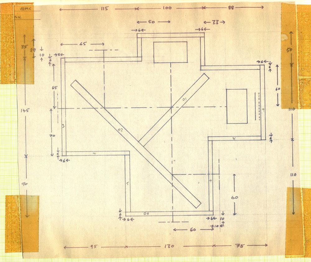
Original Plan view drawing of UKIRT diplexer design. |
During the first few months of 1980 I’d been able to design a quasi-optical diplexer system for UKIRT. The previous benchtop test design had let me find and correct various minor problems so we were fairly confident the design was optimised for its use. At that point we sent the drawings I’d made for the UKIRT system’s metalwork to Cambridge for them to machine and assemble in their workshop. This was, I think, because the QMC workshop was quite busy and we wanted to use their time on some critical items like the machining of frequency multipliers for the system. However having become happy with the UKIRT design I had started to wonder about questions like, “How small could a quasi-optical system be (in terms of wavelength) and still work well despite the effects of beam diffraction getting worse as the size was shrunk down”? As a result I also started to design what I came to call a ‘minidiplexer’ simply to see how far the design methods I had evolved could be pushed.
When the UKIRT design arrived at QMC after being machined and assembled at Cambridge, though, the performance when tested proved to be very poor. It simple didn’t work as planned. However upon inspection it became clear that what we’d been given wasn’t in accord with the set of technical drawings I’d sent to them. The various optical elements weren’t aligned on the correct axies as specified in the drawings. And the central ‘Tee’ was fitted into the box the wrong way around! As a result, I visited the QMC Physics workshop and they used the same drawings to make a diplexer that was constructed correctly and accurately. This then, thankfully, worked as well as predicted. The resulting system then was as shown in the photos below.
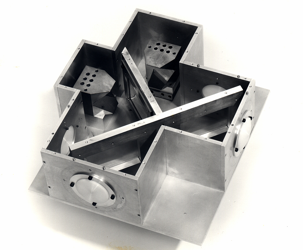
UKIRT Diplexer with lid and feed-horn arms removed |
The above photo shows how the internal ‘Tee’ holds the wire-grid polarisers and the way the various optical elements align.
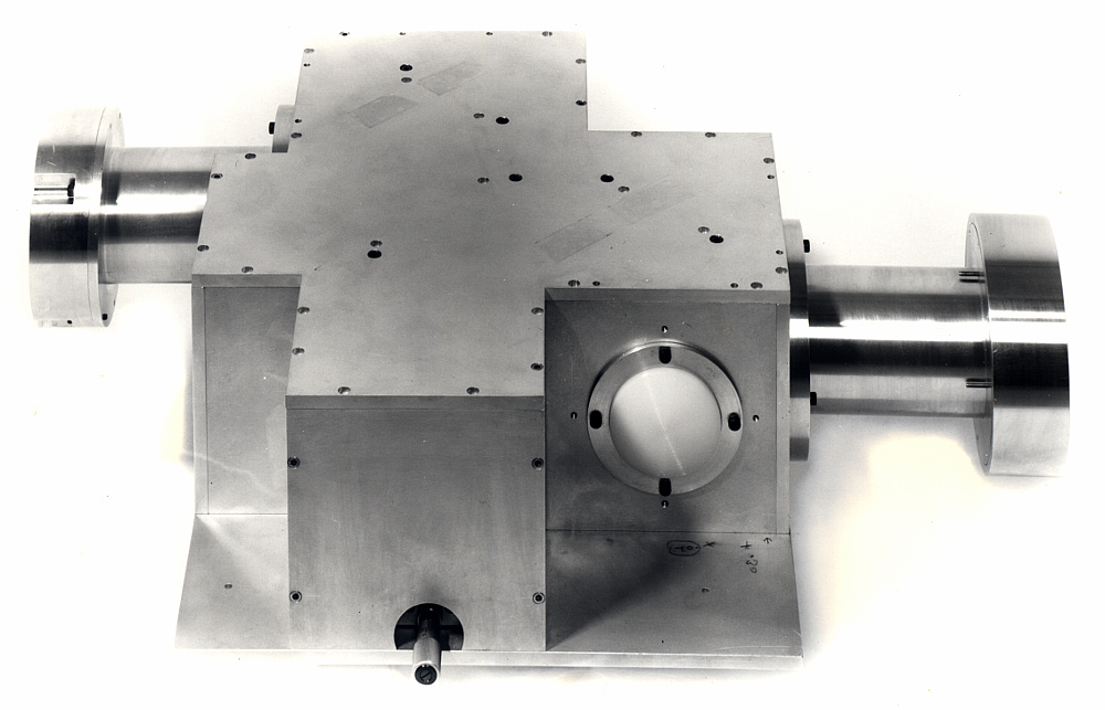
UKIRT Diplexer external view. |
The above photo shows the fully assembled UKIRT diplexer. The tubular arms are to mount the receiver (mixer) and local oscillator (multiplier). They then hold them in the correct locations, optically. The large round end-pieces on these arms are screw-threaded to allow the precise distance from their lenses to be adjusted in use to optimise the performance. These were added as a result of the experiences with reflections provided by the benchtop prototype. The face closest to the viewer also shows a micrometer which was used to ‘tune’ the system by moving one of the roof mirrors to match the chosen difference in frequency between signal and local oscillator.
In principle the UKIRT diplexer arrangement was capable of working well over the entire range from about 100 GHz up to well over 500 GHz (500,000 MHz). But in practice the performance would then be affected by factors like the choice of the ‘feed’ antennas used to couple the mixer and local oscillator. The lenses also had a pattern of grooves machined into their surfaces which helped to prevent unwanted surface reflections. These grooves needed to be about a quarter-wavelength deep to minimise unwanted reflections. A process called ‘blazing’. So a chosen set of blazed lenses would work best within a limited range of frequencies centred on their nominal design value. For UKIRT the standard lenses were based on assuming operation in bands around 230 and 345 GHz. These values were chosen to suit the spectral lines of carbon monoxide which is often found in astronomical gas clouds.
The system was eventually integrated at the Cavendish Lab in Cambridge, then shipped out to UKIRT. However before this the development process had often involved various parts of the system being shipped from one lab to another so people could check various aspects of the design, etc. On one occasion the local oscillator system had been sent to Cambridge for a while and then was returned to QMC. We then powered it up again. During this test I decided that we needed to add an item to the waveguide run between the klystron and the multiplier diode. So I undid the waveguides to insert something. At this point I attempted to make a brisk involuntary backward somersault!
When I recovered I investigated and found the reason. The klystron was powered by a high voltage DC supply. It had an internal cathode biassed to about -2 kV and a metal body which was the anode and was grounded. In appearance the klystron looked a bit like a matchbox or two, made of metal, painted red. But this metal matchbox was the outside of the anode. In normal use this was always grounded and hence held at zero volts. To ensure this, there was a tag bolted on the side which lead a thick wire to mains earth. However this bolt was also used to attach a sensor that monitored the temperature because the klystron needed to be kept cool to avoid it overheating in use. (The block also had water run though it to keep things cool.) Unfortunately, someone at Cambridge had undone this bolt for some reason and not then refitted the earthing tag when they’d done the bolt up again.
This wasn’t noticed at first because the metal waveguide was also earthed. Hence it had been grounding the klystron anyway... until I undid a waveguide flange and pulled the two sections apart. At that point I had a klystron anode in one hand and earthed metal in the other. Add a -2 kV supply to that arrangement and I was very lucky to just find myself trying to act like a circus tumbler! If my hands had clamped onto to the metalwork I’d have been dead. A telephone discussion took place shortly afterwards emphasising that anyone who ever undid that bolt should also make <expletive deleted> sure they always put the tag back and did it up again to ensure safe grounding.
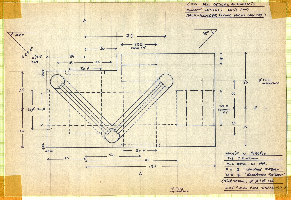
Plan view drawing of Minidiplexer |
The Minidiplexer was quite different in construction and used much smaller optics. The lenses were only 30 mm in diameter and – instead of a duralumin box and ‘Tee’ – the body of the Minidiplexer was milled by the QMC Physics workshop out of a solid block of perspex. Despite much higher levels of diffraction arising internally due to the narrower beams, this minidiplexer actually delivered better performance than the UKIRT system! In particular, it had a much lower signal and local oscillator loss level. Mainly due to it being possible to machine the smaller lenses so that they were thinner on-axis than the UKIRT lenses.
The easiest way to indicate just how small the Minidiplexer was in functional terms is to consider it in terms of wavelengths. The wavelength of a 230 GHz signal is about 1·3 mm. So the lenses in the minidiplexer had a diameter of 23 wavelengths. To maximise performance the actual beams were tailored so the bulk of the power was confined to the central part of each lens with an effective diameter of around only 10 wavelengths. If a similarly compact system had been made to operate on visible light that would have scaled down to a few microns. And the device would have been smaller than a grain of salt! Hence it was an extreme test of the Gaussian Beam Mode theory employed to create the design. Yet it performed better than a larger device (in wavelength terms). Quiet a nice vindication of the theory behind the design.
Unfortunately, the optics were so small that they would not have suited the UKIRT optics without adding other adaptor lenses or mirrors which would have lost this advantage. So, for UKIRT, the design I’d tailored for it remained the best choice for the telescope.
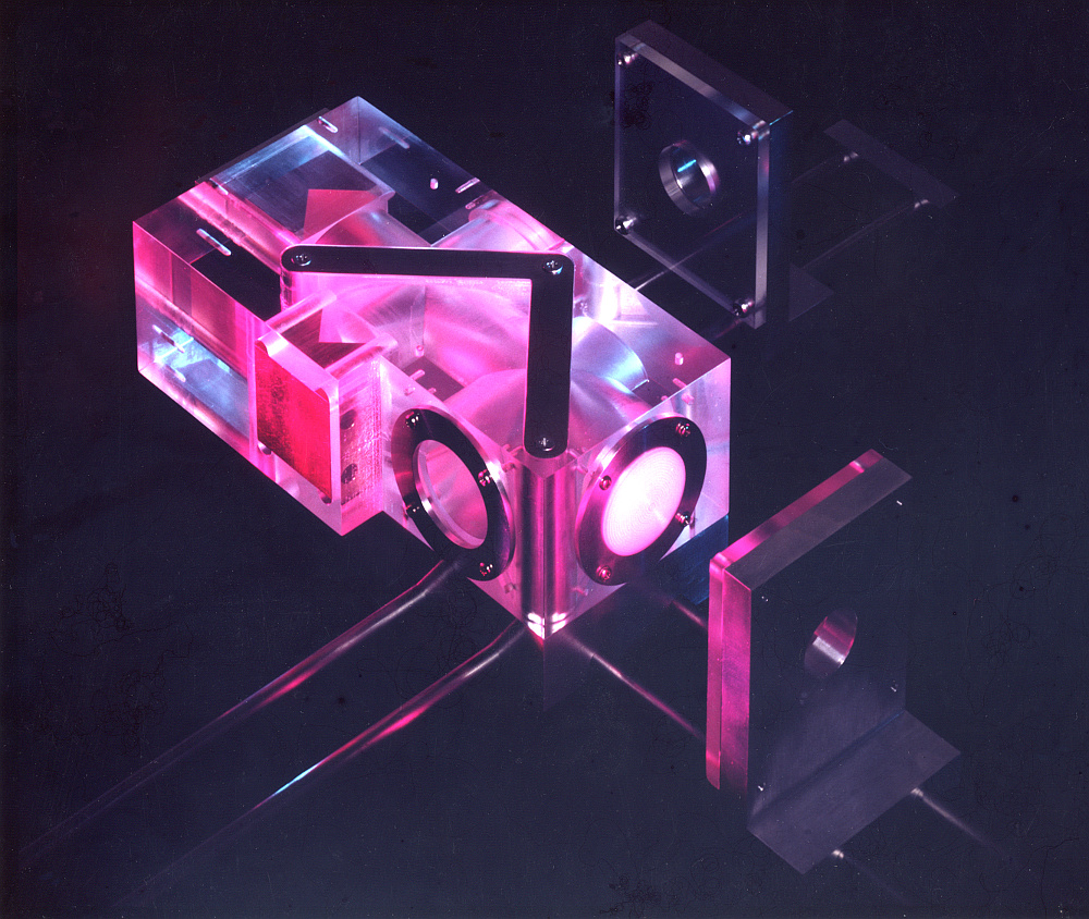
Photo of Minidplexer |
One unscientific advantage of the minidiplexer was it looked very good! The above photo brings that out as a result of shining red and blue lights on it from different directions. I have designed various instruments over the years, but have a particular liking for the Minidiplexer. It pushed the Gaussian Beam Mode ideas I’d been using as far as theory allowed in terms of trying to make a system as compact as possible with the highest performance. It also used an unusual construction method. And, to me at least, it looked superb. Form followed function. Alas, I have no idea where the minidiplexer may be now. Almost certainly binned many years ago. But for some time the QMC Physics workshop had put it proudly on display in a cabinet outside their workshop as an example of work they wanted people to see in order to show off how skilful they were as machinists. I did once wonder if I could sneak it into a Gallery 273 exhibition with a label and present it as a work of the sculptor’s art.
3500 Words
Jim Lesurf
16th Jul 2017