Summit of Mauna Kea viewed from UKIRT |
Hawai’i - High life and grass skirts...
|
Summit of Mauna Kea viewed from UKIRT |
On the 17th of June 1980 I arrived in Hawai’i for the first time. The receiver systems had been dispatched, and after years of development we had reached the point where the equipment was to be commissioned for use on UKIRT. During the weeks leading up to the trip I had organised my flight details and sorted out the data for the astronomical objects we intended to observe. I’d also spend time learning how to maintain various parts of the system. A group of us were going out. But in practice not all of us would be at the telescope all the time. So some skill-sharing made sense.
This was my first long-distance trip. In the past I’ve never flown any further than the Canary Islands. So it was quite an experience to take a direct flight from London to the West Coast of the USA. From maps I’d known that North America was big. But despite that nothing prepared me for finding that I was flying for hours and hours over land that seemed to go on forever, and also seemed almost totally devoid of people. The flight from the West Coast to Hawai’i was also unexpectedly novel for two reasons.
Firstly, at the time United Airlines were engaged in a commercial battle with some of the newer lower-cost American airlines. They were competing to get the lion’s share of the increasingly lucrative tourist traffic between the mainland USA and Hawai’i. They wanted travellers to prefer UA. As a result the quality of service and amount of the food on the UA flight to Hawai’i was amazing. It was like being given a superb exotic banquet as we flew over the pacific ocean.
The second surprise was less pleasant. As we approached landing the cabin staff walked along the gangways spraying us all with some unpleasant smelling insecticide! When I asked what was happening it was explained that much of Hawai’i was an important National Park and the regulations required this to help prevent any invasive species from reaching the islands and altering the ecology. I think we were also warned about attempting to take any food with us onto the island.
Usually, when professional astronomers go to use a telescope they arrive with a list of the astronomical objects they want to observe which have been selected with the aim of learning more about those objects. However for the commissioning trip our interest was in getting the UKIRT Receivers – System A and System B – working and calibrated. Hence the list of astronomical items I’d assembled was dominated by an ephemeris of the positions of the major planets and the Moon. The ephemeris detailed where in the sky each object would be at any time so we would know when they’d be above the horizon and thus observable.The planets would act as ‘point sources’ to check the antenna (i.e. telescope) beam pattern. The Moon was to be used as an extended object that would fill the beam as well as possible. (In practice it only about half-filled the beam at 230 GHz.) Looking at these objects would then allow us to adjust the system to optimise and calibrate the behaviour for future use.
By the time of the trip I was familiar with the usual calibration routines involved and with how to get the system running, tuned, etc. Most of this was fairly straightforward. But there was one vital delicate part which I’d spent time learning about. This was the frequency multiplier that Nigel Cronin had developed and built for use as a part of the Local Oscillator (LO) chain. In practice there were two kinds of these. One was a doubler, the other a trebler – i.e. given input from, say, a 115 GHz klystron, one would output 230 GHz and the other 345 GHz. Knowing how to maintain these and keep them working was a practical skill that turned out to be significant during the trip.
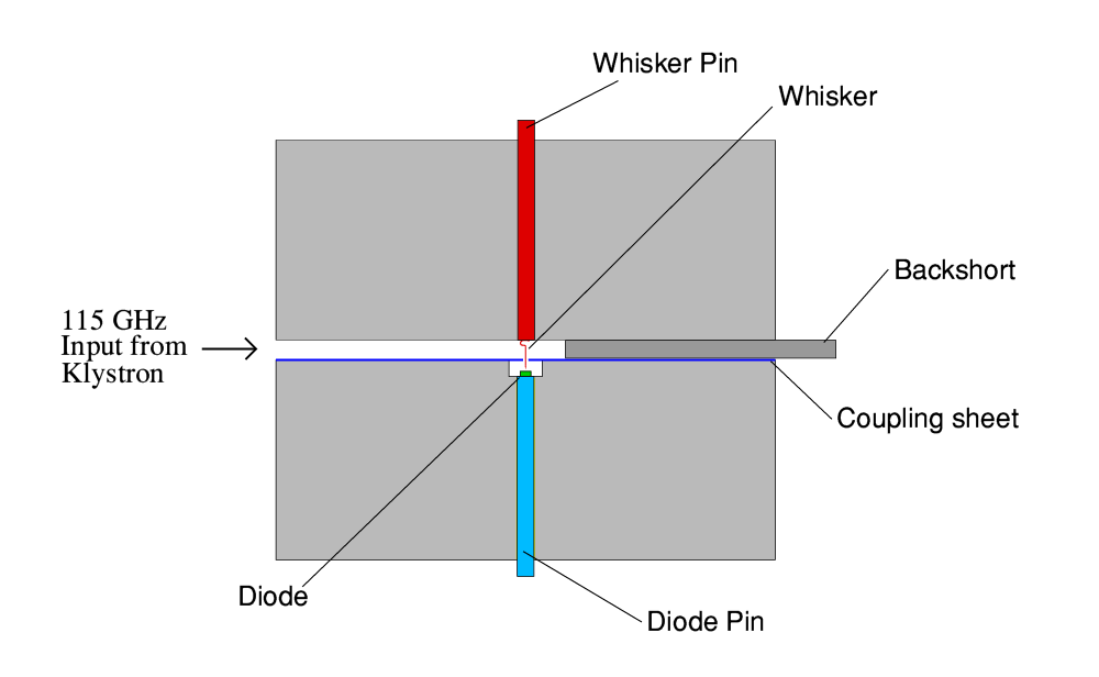
Diagram of crossguide multiplier |
More than once during the trip the multiplier featured in events. So it’s worth giving a brief explanation of what it was like to set the scene. The above is a schematic of the device. It consisted of a pair of ‘crossed’ waveguides. One of which had a diode fitted on the head of a pin. Here the diode is represented by the small green rectangle, on a diode pin shown in blue. This waveguide was oriented so as to run in and out of the page – i.e. the view here is along its axis. Above it was another waveguide running left to right. This is where the 115 GHz output from the klystron entered. Another pin came down from the top (shown in red) and on the end of this pin was a thin ‘whisker’ of wire (also shown in red). This wire had a small bend which acted like a minute spring. The tip of the whisker was etched to a point. Both pins were a tight fit into their holes. What mechanical engineers call an ‘interference fit’. Between the two waveguides there was thin sheet of metal with a tiny hole located where the guides crossed – just above the diode. The system was first assembled without a whisker pin or whisker present. A whisker was then gradually pushed into its hole until the whisker just contacted the diode.
These days whisker contacts are rarely used in electronics because they tend to be very fragile. However they offer the advantage of having a very low capacitance and this can be very useful at high frequencies. In 1980 this was the only way we had to make an efficient multiplier that would allow us to take in 115 GHz and output enough 230 or 345 GHz to operate the mixers. Great care had to be taken when making the whisker contact. The process was done using a chuck driven by a large micrometer, slowly, by hand. All the time watching a curve tracer for any sign of a diode contact. If the whisker wasn’t pushed in enough, you got no contact. However pushing it just a matter of microns too far, and the whisker point might bend or flatten or you would spear the diode. The result was then useless.
The diode chips did have about 100 diodes on them, so you could try again. But if you’d flattened or bent the whisker you have to remove it and use a fresh one. For that reason we tended to travel with a set of whiskers that Nigel had made in advance, as well as taking supplies to be able to make more whiskers, etc, if needed. Despite this, the QMC people had become accustomed to using the multipliers so could generally use them without problems. Although there was a risk the contacts might be damaged in transit because they were so fragile. And in practice different multiplier blocks were used for doubling (115 to 230 GHz) and trebling (115 to 345 GHz) because they required different output waveguide sizes.
View of some of the huts at Hale Pohaku base camp |
UKIRT was operated by the Royal Observatory Edinburgh (ROE) in conjunction with the University of Hawai’i using an office in Leilani Street, Hilo. This office and the telescopes are on what Hawai’ians call “The Big Island”. This is because the term “Hawai’i” can mean the State, or the group of islands in the chain, or the “Big Island”. Chances are that most people in Britain will think of places like Pearl Harbour or Honolulu when you say “Hawai’i”. But in fact, both places are on the island of O’ahu, not on Hawai’i island! And most tourists go to the smaller islands in the chain, not Hawai’i itself.
Initially I arrived at Leilani St and awaited. During the first day there wasn’t a Bronco (USA Range Rover on steroids!) to take us up to the observatory base camp. Hence we just checked that the system had arrived and been unpacked safely. The next day (18th June) we were driven up to the base camp at Hale Pohaku. At the time this consisted of a set of wooden huts which have, I think, since been replaced with a more luxurious set of buildings. The huts were raised above the ground on wooden pilings. The design is one people tend to see in films of far away places without realising one of their purposes. Volcanic events – particularly earthquakes – are a commonplace on Hawai’i. British-style brick houses would simply fall down into a pile of rubble when subjected to even a mild earthquake. But a wooden building on flexible wooden pilings can allow the ground to shake from side to side, using the pilings like a suspension system. This doesn’t stop the hut and its contents from being rattled about, but it does mean the hut survives... and so do its occupants provided they know not to put heavy objects on shelves just above them. Hence the construction of the Hale Pohaku huts was an appropriate one for the location.
In practice the main annoyances caused by earthquakes whilst living at Hale Pohaku were that it could upset a game of pool or snooker because it caused the balls on the table to roll about. Something the standard rules of the games don’t mention how to deal with! It could also be noisy if the quake was big enough to cause things in the kitchen to rattle about or fall down.
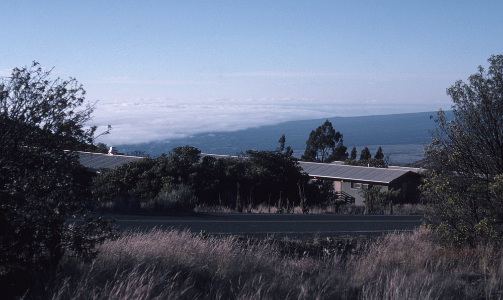
View of Hale Pohaku from a nearby hill |
Hale Pohaku is at an altitude of around 8 - 9,000 feet above sea level. The location was chosen on the basis that it was a ‘half way house’ so far as atmospheric pressure and its effects on humans are concerned. Quite simply, it is potentially dangerous to go straight from sea level up to 14,000 and expect to work. And sleeping at 14,000 feet is also very bad idea. So having a base camp at a level around 8 - 9,000 feet is advisable. As you stay there your body can get a chance to acclimatise slowly to some extent, and this helps when you work up at the telescopes. But the pressure at base camp is high enough that – for most people – it isn’t a problem. That said, I know of at least one person who was taken ill even at 8,000 ft and as a result was unable after that to ever go up to the telescopes. Nowdays this wouldn’t matter so much for astronomers because it is common to be able to use telescopes remotely. But at the time it would have had a real effect on the career of someone who had intended to be a practical astronomer.
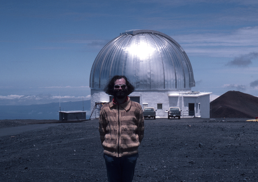
Me in front of UKIRT dome on my first day |
I did take brief trip up to the summit on the 18th, and stayed for about an hour. I didn’t feel any ill effects and took the chance to take some initial photos of the summit. The picture above shows me standing in front of the UKIRT dome on that day. There was also a lower level to the building. But this is out of sight behind the dome and down the slope. At the time the comment was that UKIRT was “The biggest telescope on the mountain in the smallest dome!”. However a few years later they rebuilt the UKIRT dome and it got a fair bit larger.
UKIRT was actually a novel design at the time. This allowed the actual telescope to be much smaller and lighter for its primary mirror size than traditional designs. It also explains why it had the biggest primary mirror on the mountain at the time, but in the smallest dome. The basic problem which had plagued large optical reflectors had been the need for the mirror surface to accurately maintain the same curved profile when the angle of the telescope was tipped. As the angle between the optical axis and vertical varied so gravity would tend to pull and try to bend the glass block of the mirror. The time-honoured solution was that when you wanted a larger mirror diameter the glass block had to become much thicker to ensure it was rigid enough to prevent too much distortion of the shape. Which, of course, meant that the weight had to go up rapidly with the required mirror size. And that in turn required a much bigger, heavier, and stronger telescope to hold it in place.
UKIRT used a radically different approach. The mirror block was much thinner than usual, and hence much lighter. Which also allowed the telescope to be small and light for the mirror diameter. Rather than solve the bending problem with sheer rigidity an ‘active’ method was adopted. The primary mirror sat on an array of air-bags, each of which was connected to a compressed air system. As the mirror tilted the pressures in various bags was altered in a way that pushed the block of glass back into the required shape. This was done under computer control. The method was complex to get working correctly. But once working, broke the traditional need for very heavy mirrors and even heavier telescopes. From this period onward, variations on this trick have been deployed to allow astronomical engineers to construct ever larger telescopes. The James Clerk Maxwell Telescope which I worked on later was another early example.
|
|
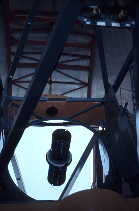
| UKIRT primary mirror | UKIRT side view |
Work started in earnest on the 19th of June. I then spent from 8am to 5pm (N.B. all time refer to the local clock) at UKIRT, mainly on helping to install the cabling required for the mm-wave receiver systems. The photos above show the primary mirror and a side view of UKIRT with the covers off and the dome doors open.
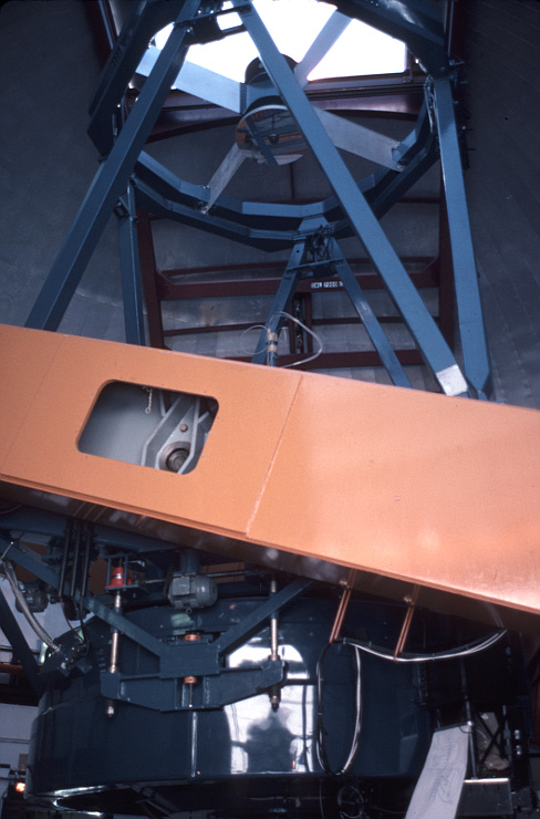
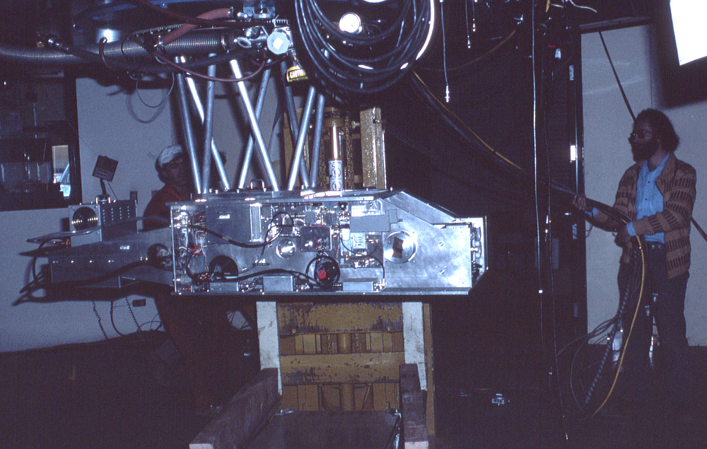
Receiver ‘coffin’ attached to UKIRT |
The photo above shows what we all called ‘the coffin’ mounted onto the back of UKIRT. I think the name mainly refers to the shape. But it could also have been a reference to our fate if – after many man-years of work – it didn’t work! Sadly, you can’t see the diplexer I designed as it is hidden away inside the coffin. This photo showed the mixer side of the coffin onto which the mixer and its associated equipment was mounted. Near the top of this side you can just see one of the circular adjusters I put onto the ends of the diplexer arms, sticking out of the coffin. Dave Vizard’s mixer (detector) is located on the centre of that.
Poking out of the bottom of the coffin you can see a tubular ‘bucket’ and some rectangular objects with electrical leads. These items are the reference loads used to calibrate the receiver. The tubular bucket contained a cone of mm-wave absorber, cooled by being immersed in liquid Nitrogen. The rectangular object with leads is a heated mm-wave absorber. The coffin included a rotary mirror that acted as a ‘switch’. In the normal operating position it reflected the signals from the telescope into the diplexer and allowed observations to be made. However it had two other rotary positions which caused the receiver to look at either the hot or cold ‘loads’. These presented known (hopefully!) temperatures which then could be used to calibrate the receiver. Once this was done, a measured output signal level could be used to determine an effective ‘brightness temperature’ value for an astronomical source being observed. (It is common for radio and mm-wave astronomers to do this and then refer to the brightness of astronomical objects in terms of a brightness temperature in degrees Kelvin.)
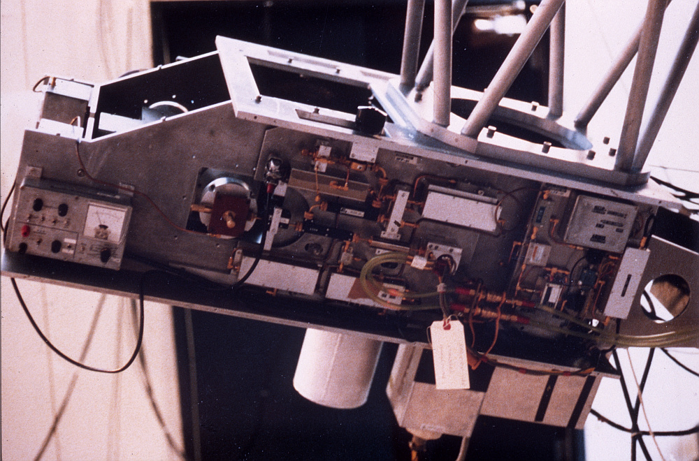
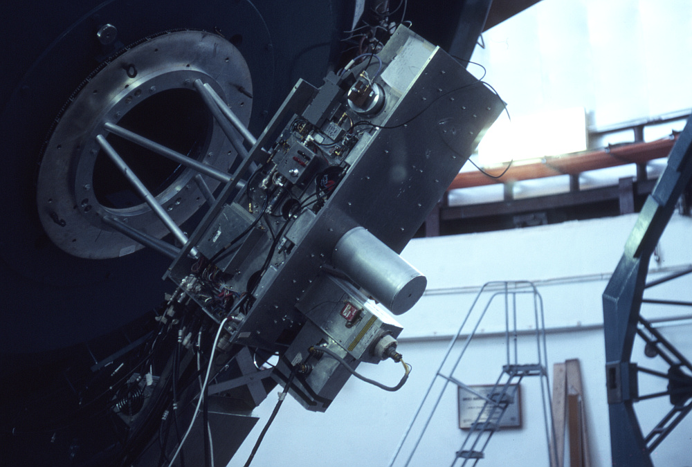
L.O. side of coffin |
The above photo shows the other side of the coffin. This was the ‘local oscillator side’. In this case you can just see a part of the diplexer though the angled opening in the top of the coffin at the left-hand end. And on the side of the coffin that is facing you, again a circular metal item is visible. On this there is a gold-coloured item clamped down by a brown plate. Poking out there are two gold-coloured micrometers. This is the diode multiplier block produced by Nigel Cronin. To its right you can see a complicated arrangement of (gold coloured, again) microwave guides and coax cables. This is the local oscillator system which included the front parts of a subsystem that was used to control (‘lock’) the precise local oscillator frequency. The paper label hanging down by some string is attached to the klystron which provides the input for the doubler. Each klystron had its own identifying label. They varied in terms of the frequency range they could cover, how much use they’d had, and their optimum operating requirements.
On the morning of the 20th I discovered that there was no water at Hale Pohaku. Richard Hills (Cambridge) said he’d heard water running during the night and wondered if it was leaking. There was no water, but I had a bottle of fizzy orange juice that I’d bought to drink. So I decided to try using that in place of water when cleaning my teeth. I then opened my – new and unopened – tube of toothpaste. Mistake! Being full it proceeded to provide clear experimental evidence that toothpaste is not an incompressible fluid. As soon as the cap was off it started spouting a worm of paste as the pressure difference caused the tube to auto-dispense its contents! I then had a bit of a struggle with this flow as I tried to put the cap back onto the tube. Having brushed my teeth I then used the fizzy drink to rinse out my mouth. Curious sensation to rinse my teeth with orange foam! If anyone had come in they might have thought I’d caught rabies. Novel way to start a working day. I then spent from 8am to 5:30pm up at summit.
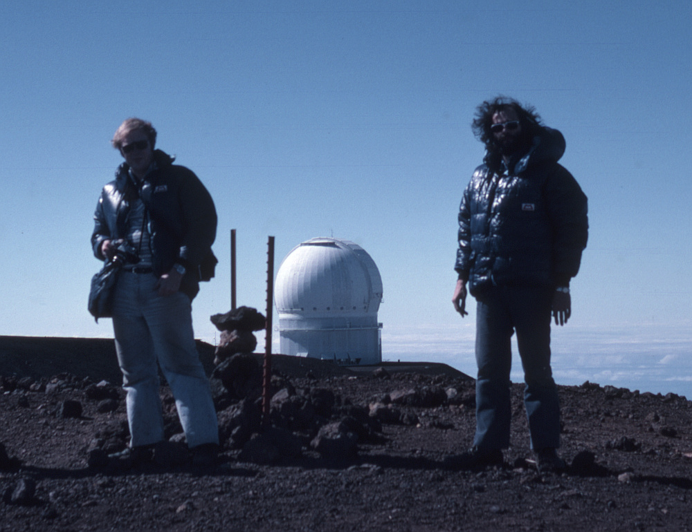
On top of the world! |
Most of the day was spent continuing to make up and install the cabling. But at about 3pm Dave Vizard (Appleton Labs), Bob Barker, Andrew Brown (Kent University), and myself decided to walk up to the actual summit which is on a peak a little way from UKIRT. Alf, a UKIRT engineering technician, suggested we wear our duvet jackets. We used to call them “Michelin Men” suits because of what we looked like when wearing them. He was right to suggest it because the peak was more exposed and distinctly colder than it was at the UKIRT dome. The picture above shows myself and – I think – Bob Barker standing either side of the marker for the summit. I’m on the right. The CFHT (Canada France Hawai’i Telescope) dome can be seen in the background. UKIRT is out of view to the left. I had to pause a few times for breath during the climb, but was otherwise fine. We got back to the UKIRT dome at 4pm. I was quite pleased and relieved not to suffer from any altitude symptoms. I’ve never been particularly fit. And when a child used to get asthma and breathing problems quite often. But if anything, after the first few days I actually found the high altitude air quite pleasing. The thin dry air seemed to actually suit me quite well. I also loved the clarity and brightness of the views.
Whilst we were at UKIRT that day Alf held up a pressure gauge exposed to the air. It showed the air pressure as being about 600 mb – i.e. about 60% of the pressure at sea level. When we got down to Hale Pohaku at the end of the day there was still no water.
On the Sunday 21st I worked at UKIRT from 8am to 5pm. I then came down for dinner at Hale Pohaku, and went back up again until 2am on the 22nd. The System A Receiver was now running but giving higher instrumental noise levels than it should. It was felt that this was because the doubler wasn’t working very well. So we tried re-contacting the diode without improving the results. To avoid wasting prepared whiskers I simply pulled back the whisker pin and then carefully pushed it in again until I got an acceptable diode curve. Since the diode chips had about a hundred diodes on them this usually meant you got a different actual diode to the one you’d contacted before. Provided the actual whisker point hadn’t been damaged it should then work OK.
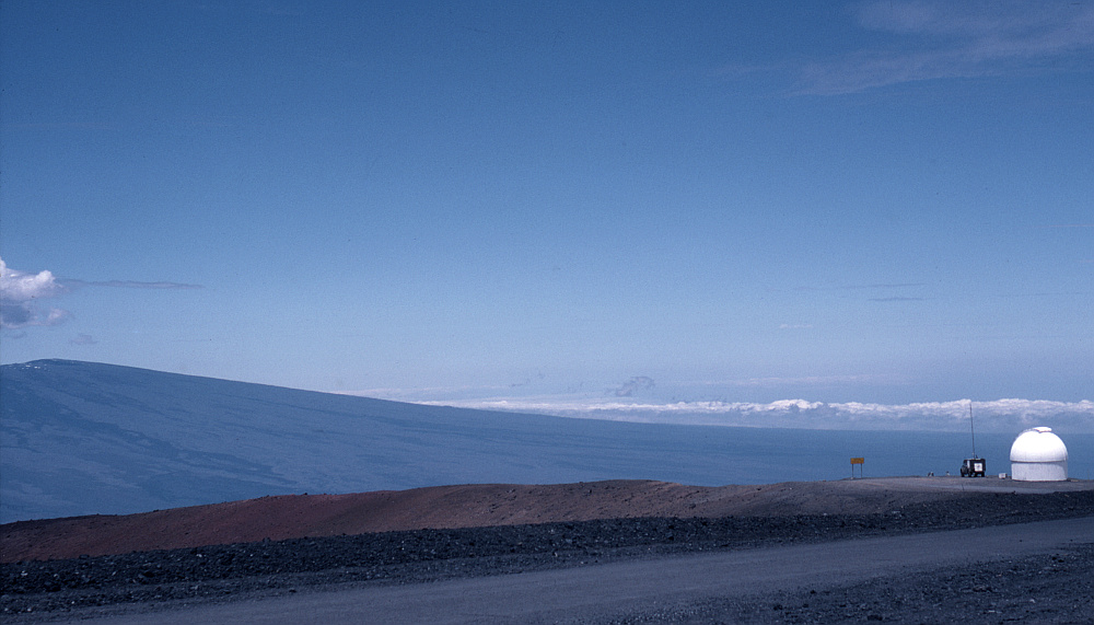
Mauna Loa |
The above photo shows a view from outside UKIRT with the peak of Mauna Loa in the distance on the left. Note how the sky looks darker towards the top of the picture. Note also the ambulance. Sometimes tourists try to drive up from the coast straight to the summit. And usually they don’t make it and need to be rescued!
We carried out some sky dips to assess the basic performance of the system and the level of atmospheric effects. The ‘sky dip’ is a standard way to check the atmospheric and instrumental conditions. Essentially, you point the telescope to look at parts of the sky where you’re satisfied there won’t be any actual significant signals from astronomical objects. Any mm-wave power you receive will then be coming mainly from the atmosphere along the telescope’s line of sight. (I’m ignoring the small amount you might get from the Cosmic Background, etc!) You then note how this ‘sky’ input varies when you raise or lower the telescope to change the angle between the direction it is pointing and the vertical.
If the atmosphere was perfectly transparent, changing this angle would make no difference. But in reality, as you tilt further away from looking vertically upwards the line of sight goes along a longer and longer path though the atmosphere. The consequent variation with angle can then be used to estimate how absorbing/emitting the atmosphere is at the time. That in turn helps you to estimate any unwanted noise contributions from the telescope itself or the receiver. So it is a standard way to assess observing conditions and the state of the receiver, etc.
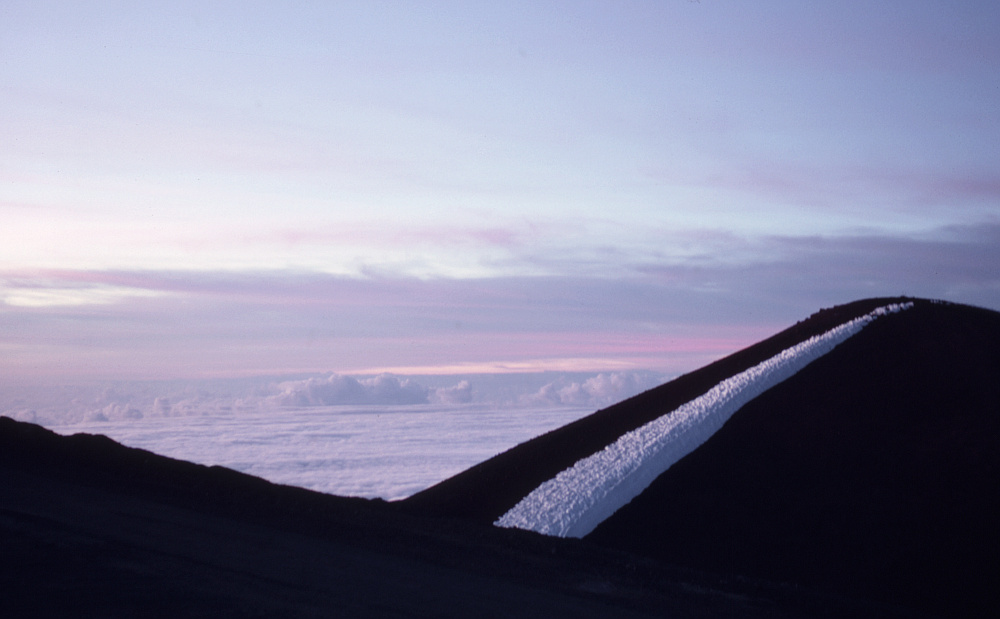
In visible terms you can see a similar effect in the above photo. The higher up the sky you look, the darker the sky appears. This is because you’re looking though a shorter path of atmosphere and seeing some of the darkness of space beyond! At dusk the same basic behaviour can produce spectacular effects as illustrated by the photo, below. And, yes, the small white blob in the top-left part of the photo below is a planet. But I can’t say which one as I’m not now sure exactly when I took the photo.
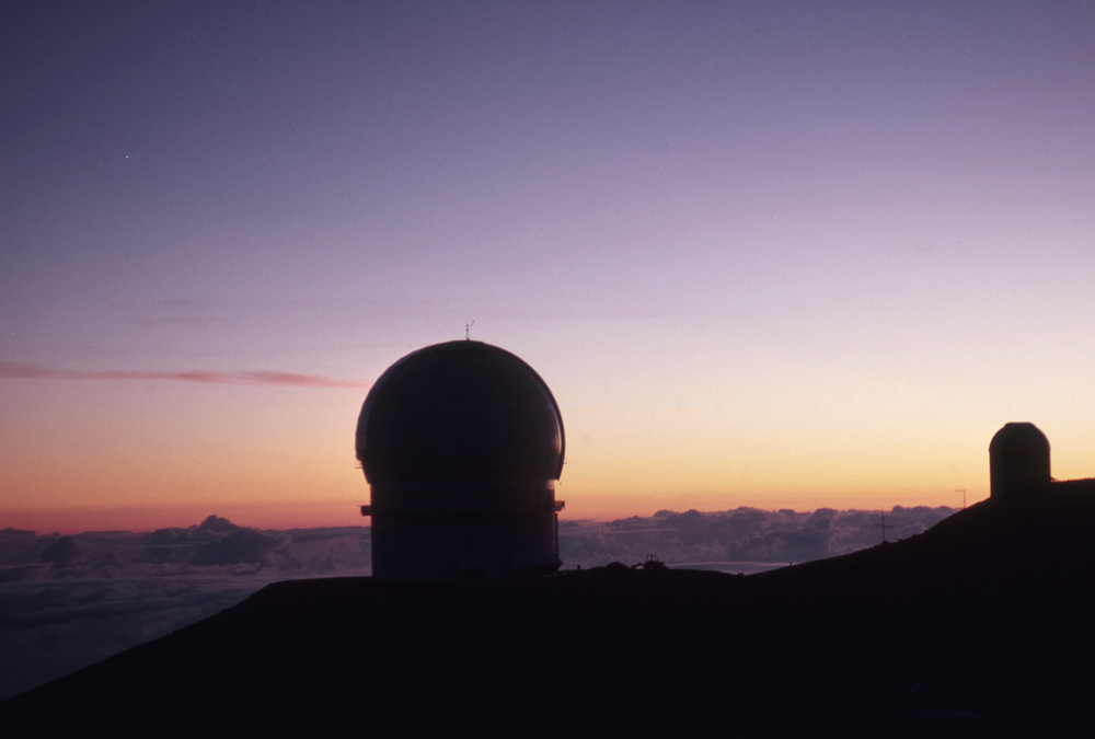
Dusk... plus a planet! |
During this period one part of the receiver system wasn’t working as it should. This was the ‘correlator’ that had been developed by Kent University and which was intended to perform spectrum analysis of the received signals. Electronic engineers can think of it as being equivalent to a highly efficient spectrum analyser. Fortunately, it wasn’t needed for most of the work on testing the optics, mixers, etc. So didn’t hold up what I was doing. Although it probably gave the Kent people some bother.
I also phoned Chris Adams, one of the QMC technicians, on the 22st whilst I was at Hale Pohaku. This was the first of a number of calls I made to her, and is a sign that I was beginning to see more of her than some of the others I’d been going out with from QMC. She would come to be a significant factor in my life...
On the 23rd the multiplier diode failed, so I tried a fresh whisker and diode. But this also failed. I decided to re-use the fresh whisker and made another diode contact. This looked OK but I’d become suspicious over the way the others had failed. So Dave Vizard measured the reverse breakdown voltage of the diode. This was only about 1 Volt which was was unusually small. Hence we concluded that this particular diode chip wasn’t in good health. We had come out with two multiplier (doubler) blocks – which with the usual staggering originality of engineers – we’d called “Block A” and, erm... “Block B”. The diode chip in Block B seemed dud, so we now only had Block A. At this point Nigel Cronin hadn’t yet arrived from the UK. He was the person who was the most skilled in this area and was coming with more diodes, whiskers, etc. I had come with some spare whiskers, etc. But Nigel was much more experienced in these things than Dave or myself. So we then used Block A until something better might turn up.
We then worked on ensuring the local oscillator system could be tuned and would lock to the required operating frequencies, etc. Because of high winds the dome wasn’t opened until about 7pm. However we were then able to make observations of Jupiter to check system performance. We continued to make further measurements and tweak the receiver system over the next day or so. One factor which caught us out initially was that one of the calibration sources was a cone of mm-wave absorbing material in a bucket of liquid Nitrogen. By habit we took for granted this would be at a temperature of 77K as that’s the usual value quoted for the boiling point of liquid Nitrogen. However we eventually twigged that this couldn’t be correct because of how high UKIRT was. The low atmospheric pressure meant the boiling point of Nitrogen was reduced. Hence we had to correct for this in order for out test results to make sense!
Me on the right, skilfully holding the cables clear |
On the 25th June work was held up for a while by an excess of astronomers! There was a scientific conference on the island and a busload had come up to look at the telescopes. So we had to close the dome and park the telescope for them to have a look around. However Dave brought the tripler (multiplier) block to try instead of Block A and this proved to be much better. During the surfeit of astronomers I took another walk and got some photos of CFHT and IRTF.
On the 26th Nigel arrived, re-worked multiplier Block B and it was then fine. Overall, the receiver was now operating well. Although on the 27th the tuning on Dave Vizard’s mixer seized up and he had to fix it. During this period there were also some gremlins in the UKIRT systems. For example, the focus drive on the UKIRT secondary developed a habit of refusing to stop once started. I also have a distinct memory of Dave Beattie and the other UKIRT people standing under the secondary mirror as it was moved to a truck for re-silvering. Marc saying “If that falls, it’ll fall on us!” Dave replying, ‘‘If it falls I want to be under it! I don’t want to be here to explain how it happened...”
Events also occurred at IRTF. For example snow managed to get into the IRTF dome during a storm. It collected and froze on the top of the telescope secondary. This finally popped it off its mount. Only some stay-wires held it from hitting the primary mirror! Being so top-heavy due to the added ice the telescope ran away. The motors then couldn’t lift it again. So the observers ran a rope from the prime focus over a crane hook and use this to pull and help the motors lift the telescope back up enough for the motors to cope! Compared to this the only CFHT problem was relatively, erm, light. i.e. They left all their lights on one night and spoilt observing for some nearby telescopes.
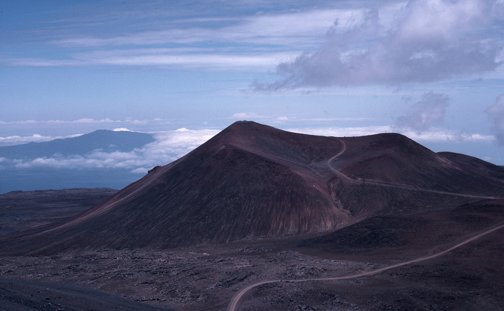
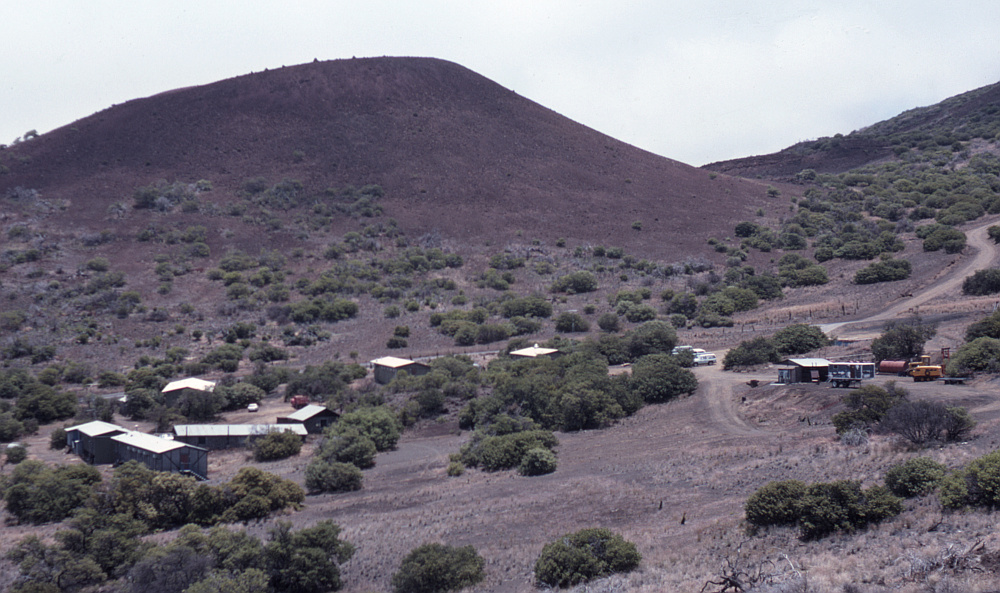
View from UKIRT of a cinder cone. I think the dip between is where JCMT was eventually built. |
I can’t now recall which day it was, but I also can remember discovering that when they say a jar of instant coffee is ‘vacuum packed’ they don’t really mean it. This revelation came from standing in the room at UKIRT where we could make a cup of tea or coffee and opening a new jar by poking my finger though the paper cover over the top. The result was, erm... a volcanic plume of coffee granules that sprayed out, covering me and everything nearby. I’d been caught out by the air pressure at altitude being much lower than inside the jar. For the rest of the day I could get a taste of coffee by rubbing my hand over my beard to collect some granules.
During the next few days the receiver system continued to work fairly well and we took calibration measurements of various kinds, altering the frequency the system was tuned to detect, etc. My last day using the telescope during this trip was on the 1st of July. If you have read the pantos page you will know that I’d been going out with various women who worked at the QMC physics department. In particular I’d gradually been getting to know Chris Adams better and spending more time with her. I phoned her a few times during the trip to see how she was and let her know how my trip was going. On the 1st of July she told me her house had been burgled during the night! The glass panel in her door had been broken. She said she was OK and nothing much had been taken. It was a worry as she was living by herself at the time, but the worst was over. I and the others had pre-booked our tickets so we could spend a few days after working on UKIRT to have a holiday. Since Chris insisted she was fine, I stuck to the plan, being aware that I might never get the chance to visit Hawai’i again!
I packed my bags at Hale Pohaku at about noon on the 1st July and went down to Hilo on the coast. Checked into the Sheraton hotel in Waiakea Village. Stayed the night there, then drove around the island to Kona. We drove around the south shore of the island so we could visit some of the volcanic sites along the way.
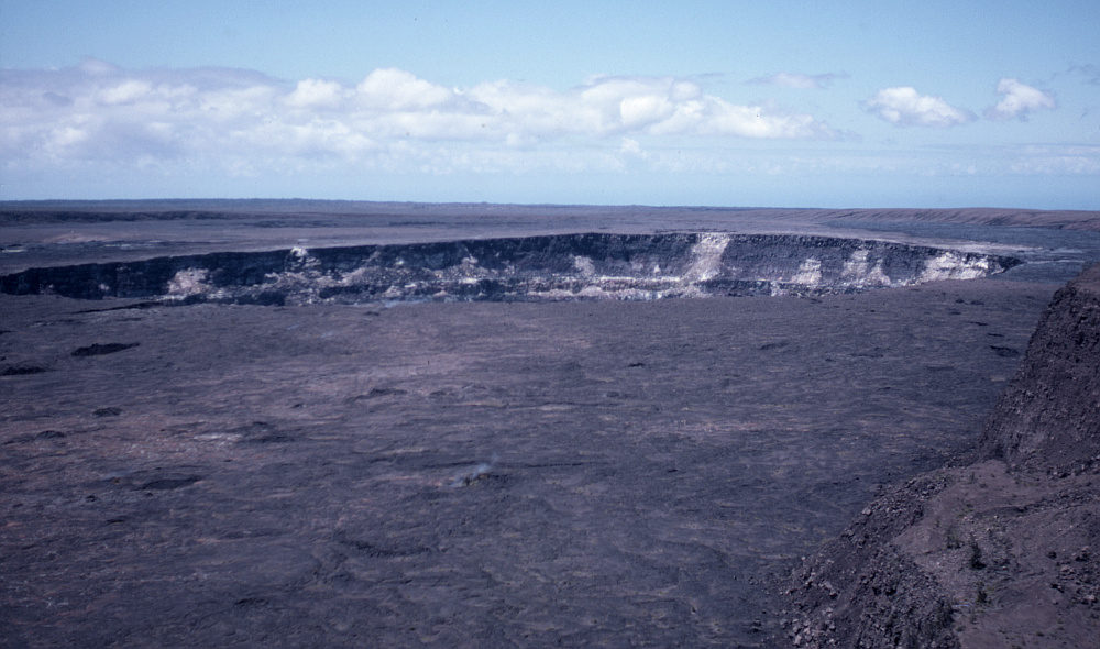
Kilauea |
We visited the Kilauea volcano which is near the south-west coast. The photo above was taken from the rim of the Kilauea caldera. Alas, a flat photo doesn’t really do justice to the sheer size of what can be seen. The main caldera whose rim I was standing on is about 5 kilometres across. The crater you can see in the photo is a smaller one only a few km across, located out on the caldera. Given the amount of volcanic activity the scene may, by now, be quite different!
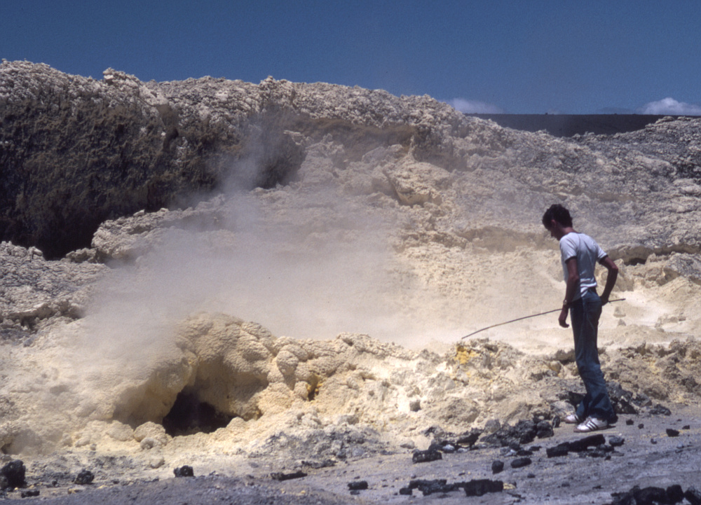
Strange rabbit holes! |
Further on we decided to get out of the hire car and take a walk. Officially, people are strongly encouraged not to do this. In this area the rock even a short way below the surface may be red hot or lava flows may become exposed. So a walk is dangerous. But with the confident arrogance of youth we decided to have a look. The above photo shows Dave Vizard having a poke at a sulphur vent with a sampling pole which was laying nearby – presumably left by volcanologists. Having survived we checked into the Kona Surf Hotel on the 2nd July.
The natives are very friendly... |
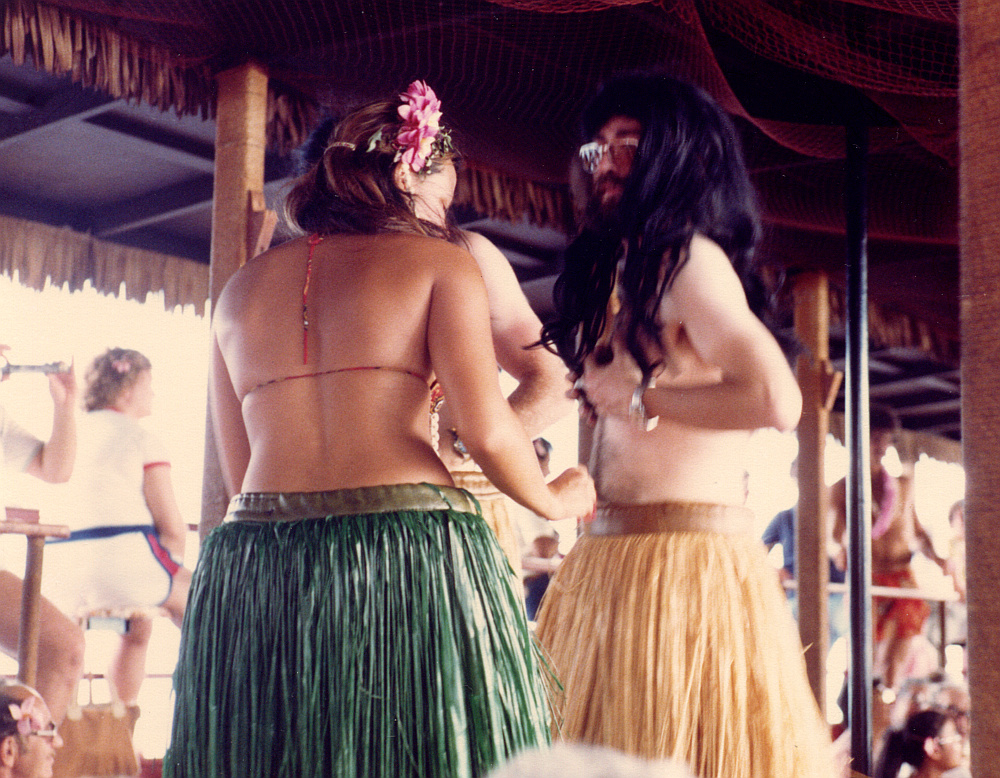
During my stay in Kona I met a woman from Kansas called Mary Jane Butler who I got on with quite well and saw a number of times. One nice feature of the end of the trip was being in the USA and going to a Hawai’ian 4th of July party with fireworks, rock bands, etc. Also at some point when on Hawai’i I found myself on a cruise out into the bay to watch the Sun go down along with the drinks. The cruise in question was called “Captain Bean’s Polynesian Cruise”. I was accosted by a pretty young lady and, being British and wishing to be polite, I agreed to her strange request that I should put on a grass skirt and wear some coconut shells. The above photo shows her kindly helping me into my costume.
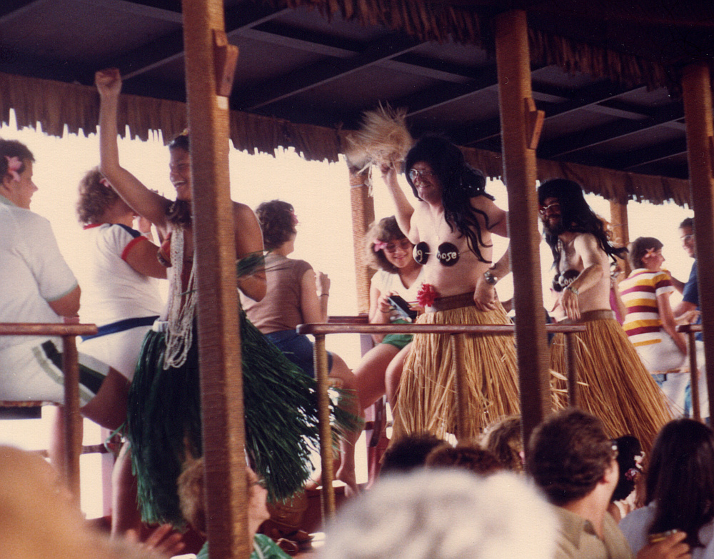
Blending in with local customs... |
I, and another member of the cruise, were then lead into dancing around the boat. For reasons I can’t quite recall, the coconut shells had the words “hang loose” on them. A common phrase on the island, I believe...
In all, I thoroughly enjoyed myself on Hawai’i until the 6th of July when I flew home happy via San Francisco.
5500 Words
Jim Lesurf
23rd Jul 2017