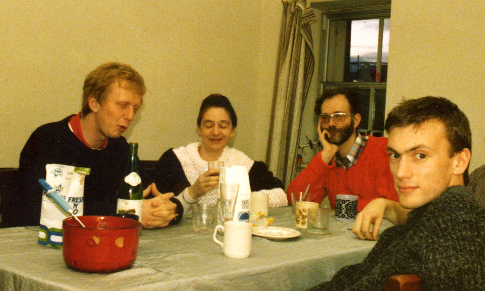
The above image shows (left to right), Andy Harvey, Chris, me, and Graham Smith.
Andy and Graham were my first research students, and survived the experience! |
Getting Better...
|
The above image shows (left to right), Andy Harvey, Chris, me, and Graham Smith.
Andy and Graham were my first research students, and survived the experience! |
During 1985 my main research activity continued to focus on the same two areas as during 1984: Waveguides and related work for the Joint European Torus (JET) project, and ‘bootstrapping’ being able to make and provide solid-state mm-wave oscillators. My interest in the oscillators had originally been prompted by working on 100 - 400 GHz range heterodyne receivers for astronomy. But having seen JET and other projects it became clear that there were various other applications where people would prefer a solid state oscillator instead of the existing vacuum-state sources.
During the first week in March I made another visit to the National Physical Laboratory at Teddington and spent some days carrying out measurements using their equipment as well as mapping out future work for them and JET. Having missed out on getting a research student in 1984 I’d been talking to Jim Birch about our setting up a ‘CASE’ studentship. At that time, Ph D studentships for topics like Physics were of two kinds. Most were the standard studentship which was generally allocated to University departments and fully funded by the relevant research council. However it was also possible to get a co-operative/combined studentship award, supported in part by the research council, and in part by some other organisation. Usually that other organisation was a UK company. But because it was funded by the department of Trade and Industry, the NPL could also act as the ‘other organisation’.
The CASE route would let me bypass the way the St Andrews Physics dept allocated studentships. This was done by a committee of academics in the dept who were established as active researchers. They chose the students. Each individual student then chose their own academic supervisor. (By a curious coincidence, the students who where chosen often then wanted to work for one of the academics on the committee! Feedback loops, anyone?...)
Unlike the above, a CASE studentship named the academic supervisor, and it was then down to that supervisor and a representative of the ‘other organisation’ to choose the student who then worked for that supervisor. In general, the research council was eager to set up CASE awards. In part because they looked good – showing the support and involvement in research wanted by others in the UK. In part because they drew some of the money required in from elsewhere.
After returning to St Andrews I had another meeting with Maurice Shepherd who ran the University’s ‘Stardel’ spin-off company. (Actually little more than a one-man-part-time-band at that point.!) After about a year of arguing around loops with the University I finally got an agreement that I could raise money to buy some Gunn diodes via an ‘Extra-Mural Research’ arrangement. Funded in part by the income from my work for JET and the NPL.
I also knew from my time at QMC that Derek Martin’s research group had, on loan, a 300 GHz backward wave oscillator (BWO or ‘carcinotron’) which I and others had often used to make various measurements. These BWOs were large and required an even bigger – 8kV – power supply. But, used with care, they were reliable. The BWO was on loan from the Rutherford Laboratory. And when talking to Derek he had told me that they actually had a row of them on a shelf, in storage. Apparently they had all been bought for a specific use, but by the time they had been delivered an alternative had been adopted. So they sat, un-used. Given that much of my previous work on the mm-wave astronomy receivers had been done in conjunction with the Rutherford Lab, Derek and I realised that I might also be able to get one on loan. This would jumpstart a lot of the work I wanted to do at St Andrews and would mean I didn’t have to keep going to the NPL to make measurements.
The main remit of the Rutherford Lab was to support UK research and the programmes supported by the Universities and Research Councils. So to me – and to Derek – it seemed natural that they would help support my work. So I contacted the relevant people at the Rutherford Labs and asked about the BWOs they had. They agreed they had them sitting unused. However their response then was to ask, ‘How would loaning them support the work being done at the Rutherford Lab?” I explained that my work would contribute to the research at various government-funded areas of science from the MM-Wave Telescope to the NPL. But it quickly became clear that the people at the Rutherford Lab had a rather narrower idea of their remit. Their mindset was that their remit was to support work which the Rutherford Lab was doing. Not that the Rutherford existed to support work carried out by the Universities or for the Research Councils, etc.
So in the end, they preferred to leave the many thousands of pounds worth of BWOs sitting on a shelf doing nothing rather than allow anyone other than themselves to use them in ways that would benefit UK research. This attitude baffled me at the time, and frankly, still does. But I fear it may be all too common in large organisations who come to feel that the outside world is there to support them, even when they were set up to support the outside world! I’ve wondered since if those BWOs ever got used by anyone.
At the start of April 1985 I was told that our NPL CASE PhD studentship had been approved by the research council. This was very good news because it meant I could now expect to get a research student and some related funding, starting the following September. It also established a clearer path for the NPL to provide financial and equipment support for the work I was trying to get going.
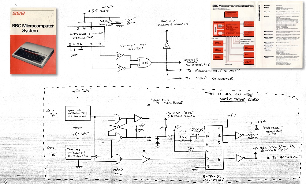
The above shows an early circuit diagram for one of the interface circuits that would eventually be used with the mechanics/optics of the interferometer. The control and data system was based on an ‘Acorn’ computer. Initially, this was a BBC ‘B’, which in later years was replaced and upgraded using an Acorn BBC ‘Master’, and eventually an Archimedes series machine. |
During this period I still had not managed to assemble a complete, working polarising interferometer system. I had a partial system, and was continuing to design, build, or buy items. But progress was frustratingly slow. This was for the reasons I’ve already described on the previous page covering events in 1983-4. Doing ‘extra mural’ contract work for the NPL / JET helped bring in some money to buy the missing kit and components. But it took up a lot of my time. Combined with the time require to prepare and start giving a number of lecture courses and an entirely new teaching laboratory also ate time. Hence I ended up with very little time for DIY equipment construction, and the department’s workshop were less than helpful.
Fortunately, I did get some help. For example, another relatively new academic at St Andrews during this time was Clivia Sotomayor-Torres. She had worked in conjunction with the now-departed ex-head of the department, Tony Stradling, and she did have some equipment. In addition to working in the same department we got to know each other via both being members of the Labour Party and having left-wing views. She had been a political prisoner in Chile under the vile Pinochet regime. But eventually she’d made her way to Scotland. She was happy to loan me some items of her lab equipment, which was at the time a real help.
At that time I had – just – managed to make one solid state oscillator that gave some mm-wave output. It was a very feeble output, and the block it was mounted in was poorly made by the departmental workshop.
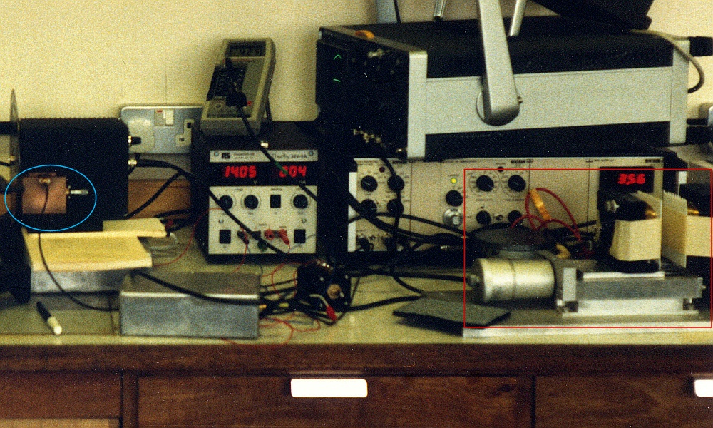
The above is a photo showing the early oscillator block (ringed with a blue ellipse) on the left of the image, in front of the chopper. The crude Fabry-Perot resonator is on the right of the image, in the red rectangle. |
Lacking the working two-beam interferometer I required, I bodged together a crude measurement system. This consisted of a Golay (thermal) detector, a beam chopper loaned by Clivia, and fairly crude form of Fabry-Perot (FP) resonator. The first mm-wave FP I put together used two sheets of the boards sold for the DIY construction of electronic circuits. These were made of a material called ‘paxoline’ which was essentially compressed paper with a filler. Sort of thick, glorified cardboard. The paxoline did transmit mm-wave radiation (albeit not very well) but the boards were fairly flat and reflected some of the incident mm-wave radiation.
By shining mm-wave radiation though the FP onto the detector I could estimate the oscillation’s wavelength by observing how the detected level changed as I varied the spacing between the two parallel circuit boards! The system had no lenses or focussing elements, so was far from a precision instrument, but it did work. The chopper that Clivia loaned to me modulated the signal at too high a rate to really suit the Golay detector, but again, the arrangement worked. Later versions of the FP (as shown in the above image) used different sheets of material and worked a little better.
In one way this was actually a testament to the sensitivity of the Golay. If anything, its main weakness was that it was too sensitive! It also would accept input radiation over a range from the visible out to the mm-wave. Hence it needed to be used with care. Even pointing a Golay at the window could let it see so much input light power that the fragile detector cell inside would be ruptured. For this reason as soon as I got the Golay detector I had covered it’s input window with layers of material to act as filters, blocking the entry of visible or infrared light. At the time you could buy expensive filters for this. But having used Golay detectors before I knew that a combination of a few thicknesses of paper and some ‘high tech’ – i.e. layers of black bin liner bag plastic – did the job OK. So I used some Fife Council bin liner and sheets cut from some old computer cards. These let though the mm-wave radiation, but protected the detector from ambient light damage. It also prevented the fluorescent lights in the lab from creating a relatively enormous unwanted output signal at 100Hz! The result was a sensitive detector for mm-wave signals.
Alas, all this did at the time was tend to confirm that the first oscillator blocks being made for me in the workshop were pretty rough. And as a consequence the results were depressingly poor. But apart from drawings of items the workshop wasn’t able to make, etc, this was all I had. Hence the need to spend weeks at the NPL to make measurements, but not – alas – on the solid state oscillators I wanted to develop.
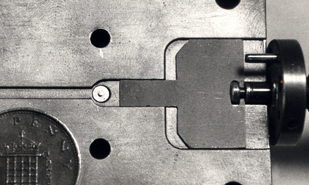
The above image shows the waveguide, etc, inside the early oscillator block which performed very badly. The output waveguide is on the left. The diode and the screw-head it is mounted on are the light-coloured circular items just left of the center of the image. The backshort is the darker grey shape to the right of the diode. |
For anyone familiar with the design of waveguide blocks the above photo will clearly show just how poorly the early blocks were made by the workshop! Ideally, the diode and its screw should be mounted in one block with the head of the screw flush with that block’s surface. The other block should have a rectangular groove which extends from the output (on the left), past the diode, to the backshort. However because the head of the workshop said this could not be made, and items often simply weren’t as specified on the drawings I submitted, the above is the result. The change in width at the diode should not exist. At the time I was told it was unavoidable. The diode screw was not centered in the countersunk hole it was meant to fit snugly into. Not was the top of the screw head flush with the floor of the waveguide as it should have been. All these problems degraded the performance.
In addition to my own electronics courses I had begun giving a set of lectures on mm-wave and THz methods as a part of the department’s MSc level course on Lasers and Photonics. The bulk of that course was based on optics and devices for the visible and near-visible regions of the spectrum. So my lectures on the techniques used at wavelengths that were thousands of times greater were something of a contrast. If nothing else, I could claim that the mm-wave region was the place to work if you wanted lots of photons. After all a Watt of optical power at, say, 100 GHz would provide many orders of magnitude more photons per second than a Watt of visible light!
On Tuesday 14th May 1985 I interviewed Andy Harvey who had applied for the NLP CASE studentship. Andy had already done an MSc at Leicester University. He had then taken on a 4-year Research Assistantship (RA) position at Brunel, which was enabling him to do a PhD. However this was in a biochemistry department where he was the only physicist. So he came to feel this wasn’t really what he wanted to be doing. He’d seen the advert for the CASE studentship and applied. It was a bold move on his part for two reasons. He had the RA for another 3 years, and could expect it to let him gain a PhD, whilst being better paid than on a PhD studentship. And the SERC (Science and Engineering Research Council) rules stipulated that if someone had already done an SERC-funded MSc they sacrificed one year of any subsequent SERC PhD funding. i.e. he would only get funded by the SERC for two years if he accepted the CASE studentship.
I was impressed by him at the interview and was confident that he would be well able to carry out the required work and get a PhD. I also guessed that regardless of the SERC, the NPL would provide further funding if the work went well. Jim Birch was also happy to give the studentship to Andy, so we I offered it to him. He accepted it in a letter dated 7th June. This was the best news I’d had so far in terms of getting mm-wave research going at St Andrews. It meant we could do much more research work for the NPL/JET during the next couple of years. That also meant we could draw in more ‘extra mural’ income for the research and for items we were able to design, test, and supply for the mm-wave experiments at JET.
During the May/June period much of my time was devoted to dealing with the undergraduate exams. Chris was still doing Open University courses, moving towards the conclusion of her Honour degree. During July she exchanged letters with her OU tutor which exposed that in the Fife region many OU graduates were actually unemployed and that positions were hard to find. Having dealt with the undergrad exams, I spent the middle couple of weeks in July 1985 working at the NPL, Teddington, and at JET. The nature of my work there had now evolved. Previously, I’d mainly been doing measurements and analysis of novel waveguide systems, potentially for use at JET. Now I was spending most of my time at the NPL/JET having meetings and making plans/arrangements for future work. Plus carrying out various design work for equipment – both mm-wave and electronics.
I continued to exchange occasional letters with people I’d come to know during my time at QMC. But I’d not heard from Jennifer Weaver – who I’d stayed with when I had visited Hutchinson, Kansas – for a couple of years. At the end of July 1985 I got a letter from her explaining that she’d discovered that her then-husband had had ‘another’ affair and she had divorced him. Not having written to me for some time, she wasn’t sure if her letter would reach me, but it brought me up to date with what had happened to her. It also told me she was now moving to Los Angeles for a year or so, then travel around. She gave me new addresses in Portland and Los Angeles where I could contact her.
I intended to write back. But when I looked for her letter a couple of days later I couldn’t find it! I searched repeatedly for days, then occasionally later on. But I only found it again many years later. It had fallen behind a chest of drawers and was completely out of sight. I did then try writing to the addresses she had given, but got no reply. So, sadly, I lost contact with her. Since then I have often thought about her and wondered if she was OK.
There is an old British joke along the lines about, “Waiting at the bus-stop for over an hour, then three buses arrive at once!”. Something similar happened to me during the time from July to September 1985. Graham Smith had been one of the students taking the Physics department’s MSc course on lasers and photonics. Graham had then been offered one of the department’s SERC PhD studentships. To my surprise he came to see me, interested in the possibility of doing a project on a mm-wave topic with me as his supervisor! At least one other project was on offer to him by another member of staff who was better resourced and established by myself.
Graham came to see me in my lab when I was using the microscope I’d bought to examine small items like diodes, etc. However I wasn’t at that moment looking at a diode. I was, in fact, looking at a microfiche of a set of photos of the covers of ancient copies of the American science fiction magazine, Astounding/Analog! I’ve always been a fan of science fiction (SF) and had first discovered the magazine from seeing a second-hand copy on a barrow in the Angel Lane market at the top of the road were I’d lived during the 1950s and early 1960s. The magazine had actually started in the 1930s but I wasn’t able to start buying new copies regularly until the late 1960s. I used to try and find second hand copies of earlier issues. However copies from the earliest years were virtually unobtainable, and very expensive. So having finally got a permanent job as a lecturer I’d bought a set on microfiche.
These days I guess that most people under the age of about 40 may never have seen or even heard of microfiches. They have largely been replaced by electronic file copies of printed material. But back in 1980s photographic microfiche sheets or rolls of microfilm were how archives of ancient printed material like magazines and newspapers were often copied and stored. The snag being you needed a microfiche reader to see them. Since I didn’t at the time have a reader, I was using the microscope! I explained to Graham what I was doing and had the distinct feeling that he would realise that I was, indeed, completely mad. Given that I also had very little in the way of lab equipment, etc, at the time I had the sinking feeling this meeting would mean he’d decide to take up an offer elsewhere...
However shortly afterwards he came back said he wanted to work as my student on mm-wave research. So I guess that either he was (is?) as crazy as me, or my MSc lectures must have been amazingly good. I now, unexpectedly, had two new research students, not just one. Given that Andy area of work was to be on devices and instruments for JET, Graham focussed on developing mm-wave solid-state sources. The only snag being that – as with Andy – Graham’s SERC support was limited to 2 years because he had already had a 1 year SERC grant for his MSc.
September 1985 was a turning point for the process of building up mm-wave research and development at St Andrews. Events soon showed that both Andy and Graham were outstandingly good researchers. Indeed, their careers since have demonstrated that they are also both better academics than myself. Their joining me, along with their funding, meant that from that September onwards, we began to make rapid progress. I can only be thankful that they were both mad enough to decide they wanted to work with me.
Graham started off by doing a literature survey, and again, we had good luck. The July 1985 issue of the IEEE Microwave Theory and Techniques journal contained a paper by Carlstrom, Plambeck, and Thornton on a “Continuously tunable 65 - 115 GHz Gunn oscillator”. We immediately recognised this was an excellent design for our purposes. The basic idea behind this design was that the oscillation frequency was controlled by the use of a coaxial cavity above the diode. This was a fairly old technique, and one I had wondered about using a few years before. But the Carlstrom et. al. example was a step forwards in two ways. Firstly, it was mechanically tunable over a wide range of mm-wave frequencies. Secondly, it was, mechanically, very well made. This allowed the diode to oscillate efficiently.
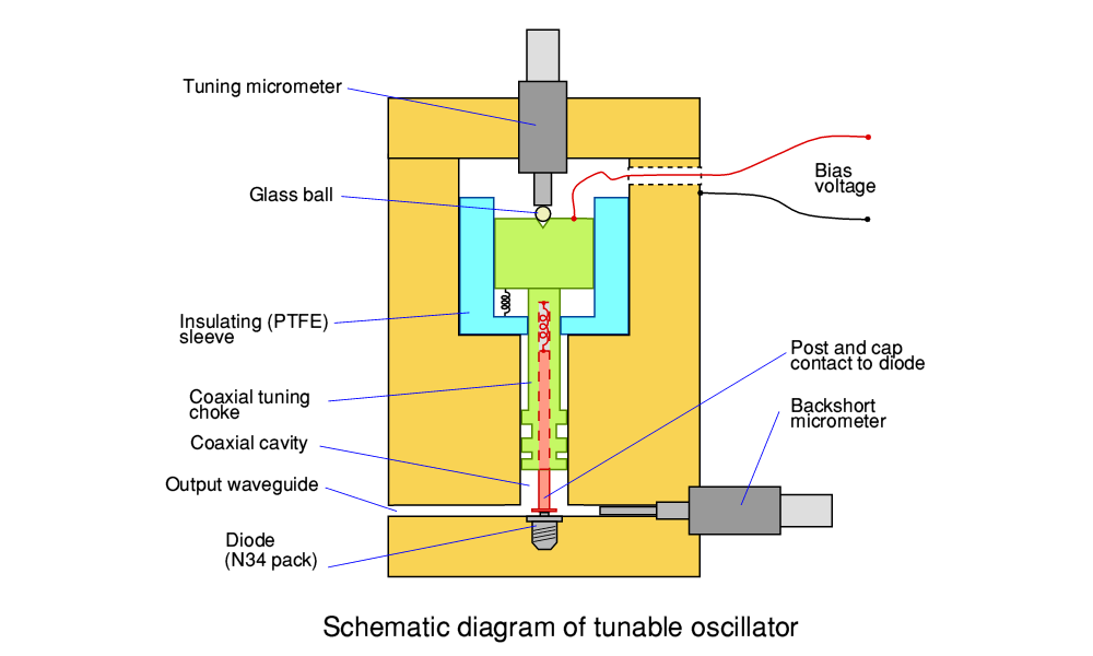
The above diagram illustrates how our modified design for the tunable oscillator operated. The section shown in green is the coaxial tuning choke structure. The micrometer at the top of the oscillator could be used to move this, up and down, altering the length of a coaxial cavity between the choke and the diode/waveguide. Contact with the diode was made via the post and cap shown in red. Compression springs maintained this contact, and the post did not move when the choke’s position was altered. Varying the distance between the diode and the choke altered the oscillation frequency. |
Looking at the design we could see a couple of ways in which it could be improved. The Carlstrom design employed a linear bearing (ball races) to allow and support the linear movement of the tuning choke. This was an expensive and delicate assembly. The bearing also centered the choke, ensuring it did not directly touch the surrounding metal block. Well controlled linear movement was important for ensuring accurate and stable tuning. The bias voltage for the Gunn diode was applied via the choke assembly. If the choke had touched the surrounding block, the bias voltage would have been grounded though the block and short circuited the supply to the diode. And any variations in the alignment might also affect the performance of the oscillator. So smooth operation and precision was required with the smallest possible gap between choke and block being maintained consistently.
I realised that the linear bearing could be replaced by a sleeve of PTFE machined so as to be a close sliding fit for the choke assembly. This insulated the choke from the surrounding block whilst allowing a smooth and aligned movement. I also realised we could employ an idea I had already explored for some simplest oscillator block designs. Back in April 1985 I’d done some drawings of a bias choke assembly for a fixed-tune design which I’d arranged to anodise, using a company I’d found in Glenrothes called Serinco. I’d spoken to their Mr Birrill who’d said we could get a bagfull of small items anodised for just 10 pounds. Hence we could process batches of chokes in this way for negligible cost.
In general, people think of anodising as a way to get a pretty finish onto smooth surfaces. However the anodising is actually a very thin surface layer of an insulating material. This made it possible to use a choke that was a close, but freely moving fit, into the tunable oscillator block. A slight touch of the choke against the surrounding block would not promptly cause a short circuit because the anodising insulated the choke. Combining the PTFE sleeve with anodising produced a design that was cheaper and easier to build than the original Carlstrom design, and the closer fit of the choke could also improve the performance!
Alas, the real the real challenge for us remained – how to actually get our modified design made well enough that it stood a chance of working as well as it should? On the Monday 8th October I submitted some drawings for a gunn oscillator block to the workshop. The chief workshop technician promptly responded by telling me he doubted it could be made there. So a couple of days later, I – along with Clivia Sotomayor-Torres – had a meeting with Wilson Sibbett which we asked the chief workshop technician to attend. Clivia was interested in the work I was doing and we had been co-operating. We both needed specialist items made for our work. We’d hatched a plan to submit a joint grant application to the SERC to fund a research technician who would be placed, under our control, in the departmental workshop. The aim being that we could get a suitably skilled person to make what we needed and simply bypass the obstructive behaviour of the head of the workshop.
Wilson had been appointed as the new head of department a few months after the abrupt departure of Tony Stradling in 1984. He had come to share my concern about the poor level of skill being offered by the department’s mechanical workshop. In my mind – and, I think, also in his – the question was approaching, “Why have an established workshop at all if it can’t actually make the items required by members of staff?” Might as well allocate the money to academic staff to buy in what they wanted, or hire technicians individually to do what they required.
I suspect that by this time the fact that I and others were beginning to think that way was starting to enter the awareness of the head of the workshop. Frankly, Clivia and I though it would be a good thing if he did realise this might be on the cards because it might have a useful effect! The prospect presented to him was of skilled technicians not under his control being put into the workshop, and their attitude and achievements then being contrasted with his own. And of course, if there was no established workshop, there might be no need for his job, either... So under some questioning from Wilson and myself, the head of the workshop started saying that perhaps one of their technicians – Myles White – might just be able to make the items we were wanting.
During October, Clivia and I put together a draft application for a grant to try and make solid state mm-wave oscillators based on layered heterostructures and quantum-well devices. In the end this didn’t get carried to completion as it was overtaken by other events. However to give some idea of just how difficult it had been up to this point to get any waveguide item made properly ‘in house’: During November Graham suggested that we try asking the workshop to make an oscillator block that had a circular waveguide profile because that only needed them to drill/ream a hole and avoided them knowing how to make rectangular grooves with square corners! Fortunately, the next couple of months showed that the efforts to try and change things were starting to bear fruit – better oscillator blocks! Also during November I spent another week at the NPL in Teddington.
During this period I also designed the initial bias power supply circuit for the gunn oscillators we would be developing. This was actually based upon the circuit I had previously designed for the power supply inside the Armstrong 700 series pre-amplifier. The main changes were that in this case the supply had to be adjustable in use. Initially this was via a manual control, but later versions also added electronic control.
During November 1985 I spent another week at the NPL Teddington. This time mainly discussing and arranging the work Andy would be doing. Given that NPL/JET had been having me working on ‘Groove guide’ one of the fruits of this was that we set about designing a two-beam interferometer arrangement where a length of the guide could be inserted into one beam. This would allow guide loss and phase delays to be measured. However at this point I was still having to use a pair of sheets of material as a simple Fabry-Perot to make frequency measurements because we didn’t yet have a working two-beam interferometer of our own. Although I had not been able to buy many high-power commercial diodes at this point we did have some devices from GEC to test. These, and some of my lab equipment, had been sent to me as a result of my previous work with Derek Martin at QMC. During December we tested an early version of the Gunn power supply and satisfied ourselves that it worked OK.
1986 started with my taking a trip to visit Ferranti in Dundee. In part this was prompted by my previous contacts with GEC, Plessey, etc, but also because they produced high power lasers and actually had an association with Thomas Keating, the company owned and run by Richard Wylde who I’d got to know, again from QMC. During January the only oscillator blocks we had remained the fixed-tune ones made in the period before the ‘fish or cut bait’ meeting with the head of the workshop. The diodes did oscillate in these, but at disappointingly low power levels. And we clearly needed both more power and the tunability of the modified Carlstrom design.

The above shows Graham’s prototype oscillator (bottom-right, standing on a block of wood) transmitting into our polarising interferometer system. I used to describe the oscillator’s overall shape and size as ‘like a tall aluminium coffee-mug’. |
In mid-February the first tunable oscillator block was given to Graham from the workshop. The initial tests showed that it worked fairly well, significantly better than the blocks they had made in the past. It was also clearly frequency tunable. We were able to make some frequency-power measurements on its tuning using an Anritsu W-band power meter Derek Martin had loaned to me and the results were promising. During March I was able to try out the oscillator with Glenn White’s InSb mixer at QMC and we got a system noise temperature of around 430 K. This was also a promising result as it showed the oscillator’s AM sideband noise level was low enough for use in mm-wave heterodyne receivers. Glenn said that I should talk with the MMT (latterly the JCMT) people as they were still looking for good solid state local oscillators. In fact, I already had this well in mind as events some time later showed.
During April I was buying 25 micron diameter tungsten wire from Mullard to wind the initial polariser grids for the new interferometer we were still designing and assembling. I then wound the grids using an old ‘AVO’ coil winder modified to do the job. I’d still not had much support from Stardel regarding finance for Gunn diodes, despite getting some by other means. By now it was clear that we would be well able to make good quality tunable sources. And failing all else, discussions with Derek Martin established that we could get oscillator blocks made by QMC Instruments or Richard Wylde if no closer-to-home route was available. However the block made for Graham gave us reason to feel that we had finally breached the way the head of our departmental workshop had previously blocked progress.
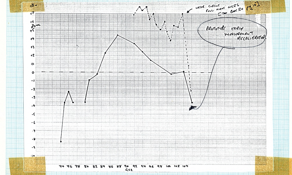
Comparison of the power versus tuned frequency of two early oscillators. |
Following the encouraging results from Graham’s first oscillator we got the workshop to make some more blocks with some modifications. One example which we referred to at the time as ‘block 3’ differed from both our tunable prototype and the Carlstrom design in using standard full-height waveguide. The waveguide in the design Carlstrom published tapered down to half the standard height at the diode. We’d initially assumed this was because it would provide better output coupling and hence produce more output power. However full-height guide gave noticeably more output than the prototype, as can be seen in the above graphs taken from my lab-book. Having seen the behaviour of these early tunable designs I also got the old fixed-tune block reworked so the diode would sit with the head of its mounting screw flush with the block’s waveguide. That oscillator also then gave more power, showing that it could be improved, and the the problems had been due to careless machining earlier on by the workshop. But by then it was clear that a tunable oscillator based on Carlstrom’s paper was going to be much more useful. So from then onwards we concentrated on our modified versions of the tunable oscillator.
In April 1986 I was stunned to receive a totally unanticipated letter from D.R. Stewart, the University’s ‘Establishments Officer’ which bluntly informed me that, “...I regret to inform you that the Committee decided your probationary period should be extended for a fourth year...” At that time newly appointed Lecturers went though a three-year ‘probationary’ period before being given tenure. This was to allow the University to check that the person appointed was suitable. I was both alarmed and angered by the letter because no one had gave me any indication that my work was felt to be unsatisfactory – or had even bothered to interview me regarding any issues. I therefore immediately arranged to see the Head of the Physics Department, Wilson Sibbett, and my AUT (union) rep, Jim Lawrence.
When I spoke to Wilson he was as surprised as I had been. He confirmed that he’d not given the committee any reason to make this decision. When we discussed my work over the time since I’d started at St Andrews it also rapidly became clear that he had not been told about the effect of Tony Stradling’s departure in summer 1984 upon my ability to carry out research. I explained this and he said he would write to the committee, objecting to their decision, and pointing out the problems I’d had to deal with which they would not have known about.
When I showed the letter to Jim Lawrence his immediate reaction was, “The aren’t allowed to do this!” He explained that the rules of the probation meant that if an academic employee’s performance was unsatisfactory they had to be told a year in advance of any such concerns and any potential action. This was to give the employee time to be able to rectify any failings before any action was taken. So to issue this letter now they would have had to warn me the previous year – which they had failed to do! He duly sent the committee a letter as my AUT representative, pointing out bluntly that the committee simply didn’t have the power to make the decision described in the letter. I also sent a letter to the Dean of Science detailing my work and challenging their ‘decision’.
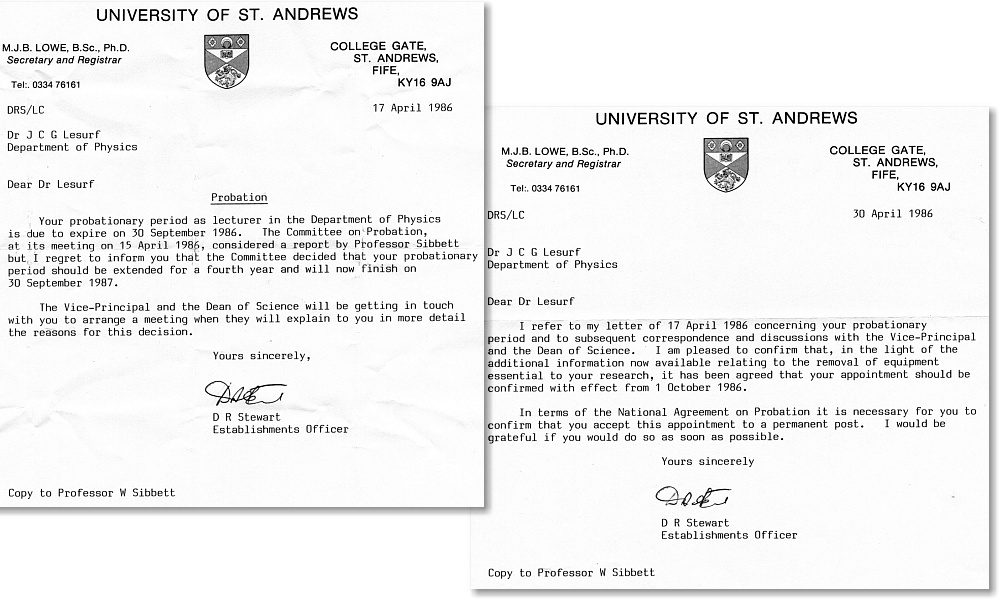
Probation letters – before and after.
|
Soon after this I was told informally that the decision would be retracted. I then got another letter from the Establishments Officer, dated 30th April informing me that, “...it has been agreed that your appointment should be confirmed with effect from 1 October 1986”. Perhaps unsurprisingly, this letter didn’t mention that the committee had exceeded its authority, and just cited the “additional information” we had provided.
I still have no real explanation for the alarming chain of events but can make two points. Firstly, that there was actually an AUT representative on the relevant committee. It was his job to ensure the rules were followed and employees were treated fairly. I knew him slightly because he used to attend Labour Party meetings. At them, his usual contribution was to fall asleep. So I wonder if he also slept though the relevant committee meetings! Secondly, a while before this ‘decision’ I’d had a stand up shouting-match row with a professor in the Physics department who I won’t name.
He was angry because he was hostile to my spending so much time on building up the teaching of electronics in the department. This was actually a primary part of my remit and why my initial appointment was as a lecturer ‘In Electronics and Physics’. I wanted to build up the practical electronics taught to undergrads. However his reaction was to shout that “Soldering is for technicians, not graduates!” I can’t be sure, but I have wondered if his opinion of me somehow got entangled with the committee’s ‘deliberations’. Fortunately, I was able to deal with the matter fairly promptly. But at the time it was a real shock to get that unexpected letter. Particularly when things were in the process of rapidly improving.
During May 1986 the Regional Council elections were held. I’d agreed to stand for one of the Fife wards for the Labour Party, so some of my time went on this for a while. I’d spoken to Wilson Sibbett about the matter to clear that it was OK with him and the University. I did my best, but as I’d explained to Wilson beforehand, the chance of my being elected was nil. Indeed, I’d only agreed to stand after I was satisfied that I had no chance because I didn’t really want to be a councillor! But there needed to be a candidate so those who wanted to vote for the party could register their views. I came in last, of course.
The 3rd of June 1986 was a landmark for mm-wave research at St Andrews. It was the first day when the two-beam polarizing interferometer Graham and I had designed and built ran successfully. This let us make our first accurate measurements on the behaviour of Graham’s prototype tunable Gunn oscillator. Over the following couple of weeks were were able to characterise the oscillator in much more detail than before. And using the oscillator we could tweak the optics, etc, of the interferometer to improve its own performance in turn.
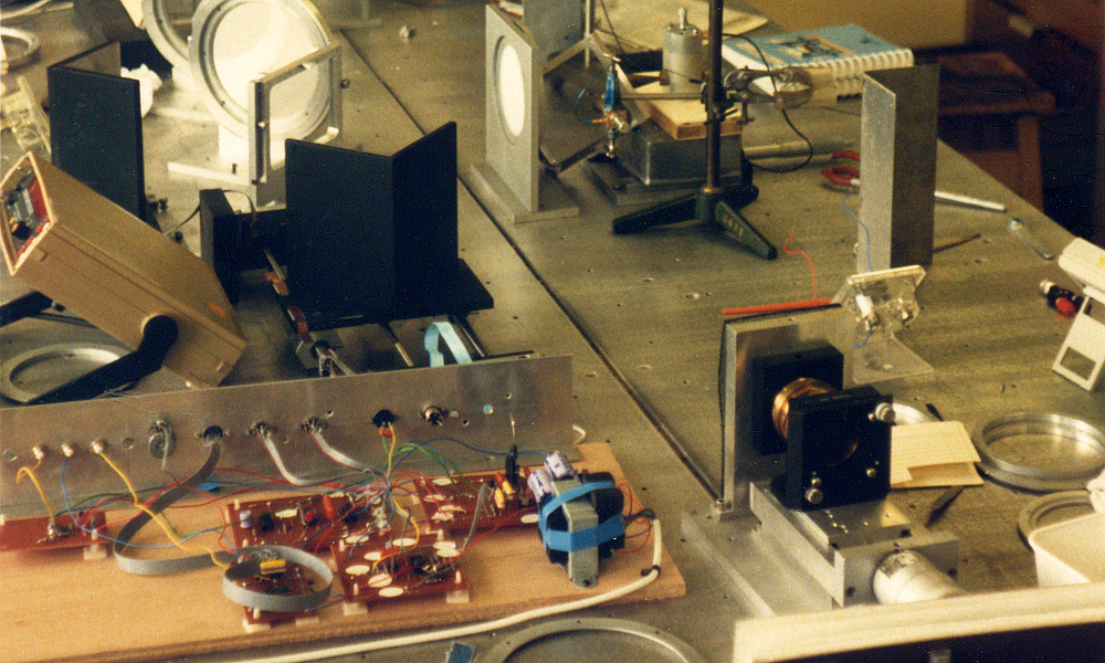
This photo shows Graham’s prototype oscillator being tested using our polarizing interferometer.
|
The photo above was taken when the interferometer was using some prototype interface circuits I’d built on what electronics engineers still called a ‘breadboard’ i.e. A set of components, etc, mounted onto a flat board of wood. You can see the electronics at the bottom-left of the above photo. The term ‘breadboard’ did, indeed, stem from ancient days when early radio enthusiasts used to build circuits with valves (‘tubes’ for those who speak American) on a genuine wooden breadboard. Once the system was working satisfactorily Graham and I got the department’s electronics workshop to construct a much better built version. The above photo also shows an improved version of the Fabry-Perot resonator, bottom-right.
Now we had both a working tunable oscillator and a functioning interferometer events began to develop more rapidly. Up to that point I’d been able to buy one batch of ‘commercial’ Gunn diodes from Varian in the USA. This used money partly provided by Stardel, but also from the funds supporting Graham and Andy. Now we have a working tunable mm-wave oscillator I was able to seek support more widely. During August I took a trip to see John Duff at EEV, Lincoln. I’d got into contact with him via other people I’d known.
Engineers in industry will be all too familiar with wild-eyed academics breezing in and presenting a story along the lines of, “With my brains and your money we could rule the world, etc, etc...” A polite meeting over a cup of tea then generally ends up with no coconut. However I was able to take a working tunable oscillator to EEV, get it out of my bag, and put it on the table. I then explained what it would already do, and say we could make more/better ones, given suitable diodes and some support. The deal being that EEV would be able to see the details of what we did in exchange for their help. Having a physical item of interest that already worked was an ace card when talking to engineers. It meant they didn’t see me as a cap-in-hand academic with crazy plans, but someone who could already get something useful made, and thus had something tangible to offer to them. I came away with the coconut. Funding for the work Graham was doing, and to buy more diodes.
This, and other meetings, also got me into contact with Mike Kelly and Nigel Couch who worked at the GEC central research labs at the time. They were trying to develop their own mm-wave Gunn diodes. Our meetings with them led to Nigel sending us batches of his experimental diodes in return for our characterising them and feeding the results back to him. This helped him tweak the manufacture of the GEC diodes and improve their performance. The outcome of my making these contacts was that we not only got money to buy diodes from the USA, but a supply of other experimental devices and support of various kinds. During the same period I had some meetings with Liz Baker (NLP/DTI) and got more support for the work Andy was doing for JET and the NLP.
As a result I could finally close down our need for support from St Andrews University’s own ‘Stardel’. I regretted this because I felt that the University really did need its own version of QMC Instruments. But Stardel was simply too bottled-up by the attitude of many senior administrators and academics at St Andrews, and wasn’t able to do what was urgently needed. (Fortunately, however, Wilson Sibbett was rather more switched-on to the value of doing ‘industrial’ work – as were some other members of the Physics dept. And things improved radically in later years. But that was much later on, not in 1986.)
By October 1986 people were contacting me about the possibility of us providing them with a tunable sold-state mm-wave oscillator. For example, I got a letter from Clive Parini who worked with Professor Clarricoats in QMC Engineering faculty about our selling them a source for their mmwave ‘compact test range’. I also set up an arrangement with Derek Martin on a ‘buy two, select one’ basis. i.e. He would pay for two Varian commercial Gunn diodes, and we’d then supply him with one working oscillator using the diode he preferred. Clive ordered an oscillator in November. Shortly after that I made another visit to EEV to co-ordinate their support and arranged for Graham to also visit them in January 1987.
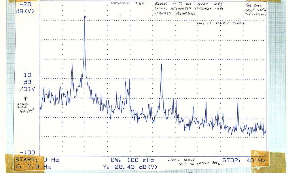
The above shows the mm-wave output spectrum of block 3 as measured using the QMC two-beam interferometer during November 1986. |
I also visited QMC whilst away from St Andrews and used their Anritsu power meter to check the output power levels of Graham’s tunable prototype oscillator and the later, modified, oscillator we’d named ‘block 3’. I was pleased to see that the measurements of oscillator performance at QMC agreed with what we’d measured in St Andrews. This helped to confirm that our own interferometer, etc, were giving reliable results. We then loaned block 3 to Clive for a few months until we could deliver the new oscillator he’d ordered.
At some point during 1986 I also submitted another grant proposal to SERC. This asked for the bits to make a high quality two beam interferometer. My main reason for this was that I wanted to replace some of the components in the system we now had, to try and improve its performance. I recall that, in particular, I wanted a high quality ‘lead screw’ to replace the length of screw-threaded rod (studding) being used in our existing instrument. I thought this would improve the accuracy of the frequency measurements. However I set out the proposal in terms of an entirely new instrument. Having learned from my previous proposal being rejected, this time I asked for rather more money to build and test the complete system. However, once again, the application was rejected. This time, the reason was even more astonishing than before!
I was told that what I proposed was “impossible” and could not be done. This was actually quite a surprise because the interferometer we had was already doing what I proposed! I was just wanting to improve this slightly. I duly took the sheets of paper outlining the reasons for the rejection down to the lab. I waved them over the interferometer and said, “Stop working! You are doing the impossible!” Fortunately for us, the interferometer ignored SERC referee’s view of reality and went on working. The basic problem here is one I encountered more than once during my career as an academic (sic?). Experts who think they know more than they do.
In almost all cases up to this point, mm-wave and infrared two-beam interferometers employed a Fast Fourier Transform (FFT) based method to make spectral measurements. In situations where the measured signals have a wide bandwidth and you have no ‘a priori’ knowledge which tells you otherwise then the general rule is that the frequency resolution of any spectral measurement using a two beam interferometer and FFT processing is limited by the range of path difference the instrument can cover. Academics often use complete measurement systems they buy ‘off the shelf’ without really fully understanding how they work. This is fair enough if they just want the results. But can mean that they don’t fully understand the situation.
The method Graham and I were using to measure the frequency, power, etc, of the Gunn oscillators wasn’t only based upon using a Fourier Transform. We did use FFT methods to get an overall spectrum. But because we knew the sources (our Gunn oscillators) were highly coherent and produced a specific kind of periodic/coherent output waveform we also used a method that was more familiar to researchers working in the visible and near visible region when examining the output of their coherent sources like lasers. This method is called ‘fringe counting’.
If you are interested in the details you can find them outlined in chapter 24 of the free book linked here.. But in simple terms the method relies upon the waveform being a fairly clean and periodic one like a sinewave or a distorted sinewave whose amplitude is much larger than the background noise. You can then determine the wavelength with much higher precision than via the standard FFT (Fast Fourier Transform). In our case, this let us measure oscillator frequencies with a precision that was more than ten times better that using an FFT. The FFT gives a useful general spectrum, so can show harmonics, or other components. But fringe counting provided better measurements of the main oscillation frequency. And worked nicely even after being told it was a figment of my imagination!
During the first week or two of November I started drawing some ‘quasi optical circuit diagrams’ of a new type of measurement system I was trying to design. At the time I wanted to be able to make accurate impedance measurements on the oscillator blocks we were using. The standard microwave kit for this was very expensive and - frankly – of limited accuracy. So I was trying to devise a system we would be able to make for ourselves. One that was inherently simpler in terms of being easier to calibrate and use precisely. This eventually led to a system which became important for me, and for Andy Harvey, a few years later...
On the 5th of December we tried out a new tunable oscillator block with a changed waveguide profile and this gave even better results that the earlier versions. So continued to make improvements to the output power, tuning, etc, available. By this point Myles was showing that it was, indeed, possible for at least some of the technicians in our workshop to routinely produce good quality oscillator blocks, etc. However it was becoming clear that many people in various academic and research areas would be interested in acquiring an oscillator. So we also found a local machining firm – Browns of Ladybank, in Fife – who machined some blocks for us.
During December I also drafted a letter to Stardel to start the process of formally ending their involvement with the oscillator work and prepare the ground for EEV ‘taking over’ commercial support. I also sent a letter to Nigel Cronin at Bath University pointing out that if I could get a quasi optical impedance measurement system running it could be used for measurements over the range from 75GHz up to above 200GHz. Hence it would be useful for his work on frequency multipliers. I also wrote to Adrian Webster (Cambridge) to keep him informed out our work because it may have been useful to support their own work on receiver systems for astronomy. So despite the alarming episode of the threat to my employment during the year, 1986 ended with a very positive note or two! (pun alert!)
8300 Words
Jim Lesurf
11th Jun 2018