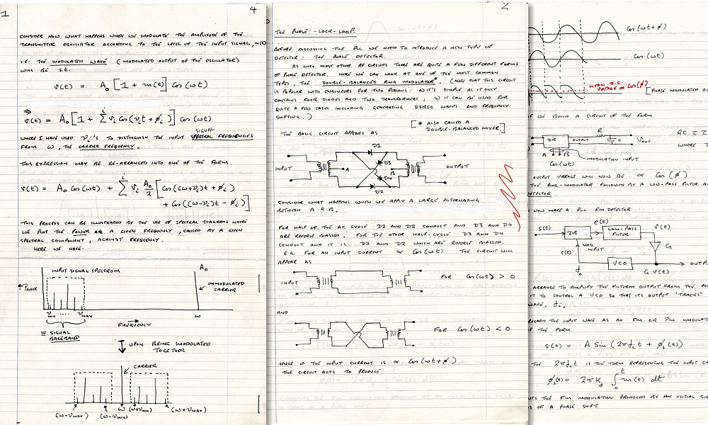
Pages from my notes for the 1984 version of “Radio Communications”. These were then photocopied as handouts for the student. |
A Bumpy Start...
The first undergraduate lecture courses I had to teach at St Andrews were “Information and Signal Processing” (ISP) and “Radio Communications” (RadCom). These were an appropriate way to get me started because they had been the foundations of much of my research work for many years. The snag, of course, was that I now had to write out a logical series of lecture notes and ensure I could teach the topics in an organised way. The ISP course replaced an earlier one on “Information Theory” which had been presented by Ian Farquhar, a theoretical physicist who had actually been at QMC earlier in his career. I wanted to expand this course to cover practical applications of the theory. In addition, I was asked to present a set of lectures as a part of the MSc course the School ran on Lasers and Optonics. My MSc lectures were to cover the basics of mm-wave methods. Hence that content also related to my research work.
|
Pages from my notes for the 1984 version of “Radio Communications”. These were then photocopied as handouts for the student. |
These days I have long become accustomed to using a wordprocessor (!TechWriter) which provides excellent facilities for wiring technical documents that include equations, etc. This makes it easy to generate well laid out printed notes. But back in 1983/4 I had to write my lectures using ye olde fountain pen and lined notepaper. This was quicker than using a typewriter or the very crude early wordprocessors then available. It made adding equations or diagrams simple because I could write/sketch them as I proceeded. However my handwriting was (and still is!) awful. So I had already for some years adopted writing things out using block letters, not cursive handwriting. With practice I became able to write quite quickly this way. The result was once described by someone as “being neither upper nor lower case”! But it was much more readable than my handwriting.
Looking at the undergrad courses, etc, I came to feel that what was really needed was a much better electronics lab course because electronics is a practical subject. Most practical physicists benefit from some ability or knowledge of hands-on electronics because they often have to fiddle with equipment to make systems they can use for their experiments. It can also save money to be able to build something rather than buy it from a catalogue. So – in addition to the lectures – I started to put together a new “2nd Science” Electronics Laboratory course which all the Physics undergrads would take. This, combined with the lectures, means I had a fair amount of teaching material to write. And my teaching load rose rapidly during the first year or so as the courses began.
I had helped to run a basic electronics lab course for the undergraduates at QMC. And I did have a small amount of experience in lecturing, at PCL. But I now had to prepared detailed courses with more lectures and in greater depth than I’d previously tackled. I also realised that to a large extent I’d made many assumptions when carrying out research and these needed checking. Quite a lot of what I ‘knew’ about signal processing and the more specialised items I’d been using for my research I’d gained from experience and explanations provided by other co-workers. However when I sat down and started to try and work out detailed explanations I quickly saw there were a number of basic points I’d taken for granted, but could not fully explain. In effect, some of what I did was based on “everybody knows...” assumptions. Fine at a practical level if they worked. But not as an explanation of the underlaying physics, and it wouldn’t help me when a student asked a “So, how does that work, then?” question!
As a result I had to spend quite a lot of time going though various textbooks and journal papers to try and understand things well enough to give clear explanations founded on the physics involved. I discovered that one of the best ways to ensure you understand something is to have to think about how you can explain it clearly to other people. In that sense, teaching is a learning experience. I did enjoy this, and have continued to do so ever since. But the drawback was that it took a lot of time.
I also discovered that I could not make sense of some of the explanations in some of the undergraduate textbooks which were in common use. In some cases this was, of course, my being dim and I eventually twigged what they were saying. But in some other cases I gradually realised that – shock, horror! – some textbooks contain erroneous ‘explanations’. This also slowed down preparing courses because I had to spend a lot of time and effort puzzling over things before I felt comfortable with concluding that a given ‘textbook explanation’ was simply wrong. It revealed that, sometimes, textbooks contain ‘explanations’ which have essentially been copied from one generation of books to another. The authors taking for granted that they must be correct. But I never felt happy unless I could make sense of an explanation or find an alternative that made sense to me in terms of the basic physics or mathematics. I learned a great deal in the process, but it used up a lot of my time during my first year or so at St Andrews.
St Andrews University and QMC differed in many ways, and the move was also something of a ‘culture shock’ for me – sometimes in a good way, sometimes not. The most obvious academic difference was that at QMC the Engineering Faculty was much bigger than any other subject. Whereas at St Andrews the Engineering Faculty, erm... didn’t exist. Some years before I’d arrived the Universities at St Andrews and Dundee had been combined, then had split apart again. When the division was made, Engineering essentially went with Dundee.
|
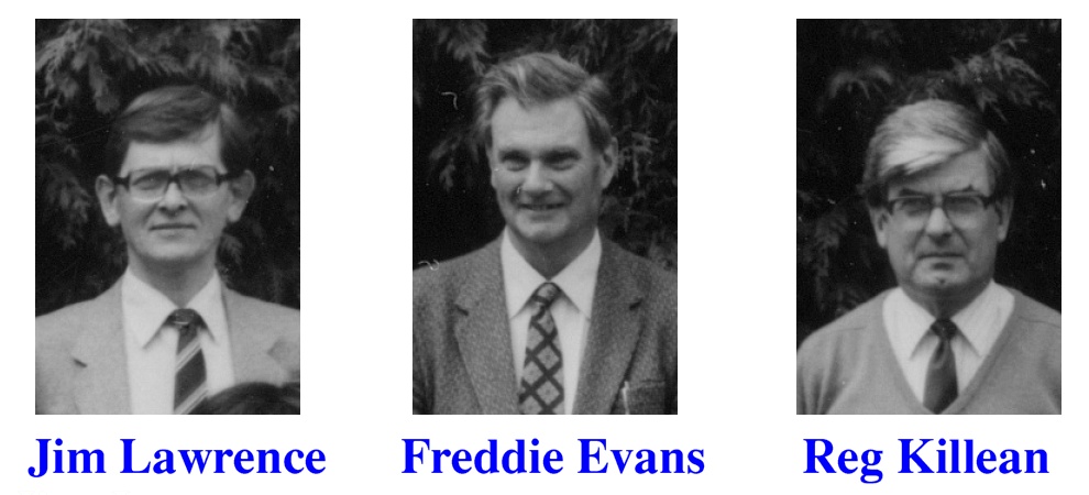
When I arrived, the undergrad teaching of electronics was mainly provided by Freddie Evans and Jim Lawrence. Reg Killean was also involved and in the installation, etc, of the department’s computer systems and other engineering-based work. My lectureship replaced Tudor Jenkins who had been teaching electronics. He had left to go to a job at a Welsh university. In practice, all the electronics teaching and research was being handled by three or four people, who – apart from Freddie – also had things to do in other areas. The plan under Prof Stradling was to expand the provision of electronics courses, etc, for undergrads.
The typical background of the physics undergrads also differed quite markedly. At QMC a large fraction of the students came from homes in the East End of London. (As, indeed, had been so in my own case.) Many continued to live at home and tended to have low-income backgrounds, and were the first person in their family to go to University. However almost all St Andrews undergrads came from other places and lived during the first year in halls of residence, etc. There was also many more students who had been to private (i.e. in UK terms ‘public’) schools and had a relatively wealthy background compared to the norm at QMC. So the social mix was quite different.
At QMC The undergrad courses were divided into two semesters, each of the same length (12 weeks). Every course had the same number of lectures per week, and had its own exam paper. However when I started at St Andrews, the lectures were divided into three terms, and the number of lectures varied from one course to another. Some exam papers were shared by more than one course. Compared to QMC this was something of a patchwork quilt.
In terms of research, the arrangement which had been made before I arrived was that my work would be in conjunction with that being done by Professor Tony Stradling’s research group. He and I had conversations about this before I made the move, as well as after I began work at St Andrews. University departments are meant to provide what tended to be called a “well found laboratory” for academics doing research in science topics. That meant I either needed access to using relevant equipment that was already there, or some money to buy the basic essentials I required. Tony Stradling had many of the items I’d need – signal amplifiers, phase sensitive detectors, infrared detectors, interferometers, etc. So part of the arrangement was that I would use some of the items he had acquired. Given this, I’d agreed with the department that they would also provide me with a ‘start up’ budget of £7,000 for equipment and another £1,000 for consumables to let me buy some specific items I needed which weren’t already available. Without the equipment Prof Stradling had, this would not have sufficed, but to fill the gaps it was fine. Given this amount I set about buying items I needed.
The main items I obtained were
The BBC ‘B’ was chosen because it was easy to program and had a good set of electronic ‘interface’ connections. This meant I could use it to control an instrument like an interferometer, and to collect and process the data collected using the instrument. In terms of practical research my initial priority was to design and build a mm-wave polarizing interferometer which I could then use to make measurements on oscillators, etc. I was still working on testing and developing solid-state oscillators for the 100GHz region, so an interferometer was the basic measurement tool I needed.
I suspect that today very few people will have a clue what a mechanical ‘drafting machine’ may be. They have been totally replaced by computer systems. But they provided an accurate way to produce engineering drawings that defined what a workshop was required to build. A good quality drafting machine made it easier to produce clear diagrams. And over the years I’d got accustomed to using one. However they were expensive.
The Golay detector was essential for the measurements I had in mind. Its working mechanism is a small thin walled glass cell. The wall was silvered on one side and blackened on the other. If you shone light (or mm-waves) onto the blackened surface the energy was absorbed and the gas inside the cell warmed up. This expanded the cell and slightly distorted the glass wall. By reflecting a beam of light off the silvered side the Golay detected this change which indicated that radiated energy was being detected. In principle, a simple idea. But it was very useful as a sensitive detector that worked over a wide range of frequencies. The snags were that it was expensive (particularly when a diamond input window was required) and quite fragile. It also tended to pick up mechanical vibrations which produced noise on the output. So had to be isolated from low frequency vibrations. The microscope was to inspect items like diodes, contact posts, etc, to ensure they were in a satisfactory state. The above items took most of the original money I had been allocated for equipment.
At home, Chris and I were organising two projects. The top priority was that we wanted to get married quite soon. The second was that we knew that – although fine in other ways – the house we had bought urgently required its windows being replaced. The existing windows were old single-glazed ones with wooden frames. And in some places the frames had rotted to the point that you could crush the wood under the paint with your thumbnail. So we started getting quotes for replacement double glazing.
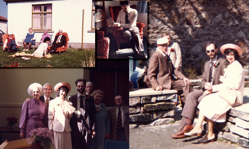
Photos taken around the time of our wedding. The photo on the bottom-left shows, from left to right: Chris‘s parents, Chris, me, my parents, and John Gilbert (my best man) on the right. |
Chris and I married one morning in April. The ceremony was held in the St Andrews Registery office in St Mary’s Place. Our parents came to the wedding. My Best Man was John Gilbert. I’d known John since I’d been at secondary school in Forest Gate, London. He was a lay preacher with the United Reform Church, and I’d promised him many years before that he would be my Best Man when I got married. After the ceremony we went to the ‘Peat Inn’ restaurant for the wedding breakfast. The Bride looked beautiful and it was a wonderful day.
My parents stayed with us for the week, and then we took them by taxi to Dundee to catch their train home. I helped them aboard the train and watched as they made their way along the carriage looking for their reserved seats. As the train moved out they continued to search for their seats until they were out of our sight. Five weeks later I received a phone call to tell me that my Father was dead. He’d had a sudden heart attack and was dead by the time an ambulance arrived. So the last time I ever saw him was as he was walking along inside the railway carriage, looking for their seats. I got the call at the start of the week just as the double-glazing company began removing our old windows and installing new ones. So we decided that I’d go down to London to stay with Mum and help deal with Dad’s funeral whilst Chris stayed in St Andrews to ensured the double glazing was installed OK. My Father was buried in the churchyard of the old church in Laindon, Essex, beside his first wife. I still miss him.
I stayed with my Mum for a few days after the funeral, but then had to leave her to get back to St Andrews. We did discuss the possibility that she might also wish to move to St Andrews. But she decided that her friends were all nearby in Forest Gate, so she preferred to remain there. This made sense because the neighbours got on very well in the block of flats, and did care about each other.
By the time I got back to St Andrews the new windows were fitted, and I settled down to get on with work, etc. During May1984 I spoke with Nigel Cronin at Bath about the trying to obtain some Indium Phosphide (InP) Gunn diodes for making mm-wave oscillators. I also experimented with the BBC ‘B’ computer I’d bought and devised some initial circuits which could be built to let the computer control an interferometer and collect/process the data. However within a few days of returning to work I was told that Prof Stradling was leaving St Andrews! He was taking his established research group – and lab equipment – with him. This drove a coach and horses though the arrangement we had made as part of my decision to accept the job at St Andrews. It was an unanticipated disaster for my research plans.
The Research Councils who were the main funders of academic research assumed and expected that the individual Universities would provide their research-active academics with what the standard phrase called a “well found laboratory”. So, for example, it was taken as given that if the researcher was working with electronics they have equipment like a general purpose oscilloscope, etc, for routine basic work. The discussions I’d had with Tony Stradling had arranged I could use a lot of his equipment, saving the department the full cost of setting up my lab. On that basis I’d agreed to initial funding that added a few other basic items I needed which he couldn’t provide. Now, that was all I was getting! In general, research projects can be used to obtain money for kit specific for a project. But not for the items you were expected to have anyway – providing them was regarded as a matter for the University.
Fortunately, unlike many university researchers, I had already formed a habit of preferring – when I could – to design and build my own research equipment from scratch rather than buying it. The advantage of buying kit off the shelf was, of course, that – if you had the money – you could get it and start using it quite quickly. But for a lot of what I wanted to do, I’d already spent some years working with people at QMC to design and develop specialist equipment for my mm-wave research. DIY would mean a slower start, but should eventually let me build better equipment for my purposes because it could be targetted state-of-the-art kit not general off-the-shelf. So DIY it was...
|
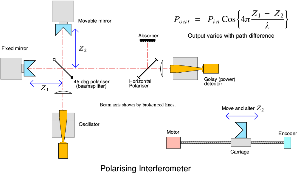
The above diagram shows the general design of a typical polarising two-beam interferometer. The input signal is split into two half-power components by the 45 deg polariser or ‘beamsplitter’. These individual components are then sent to two roof mirrors which retro-reflect them, ‘flipping’ their polarisations. They return to the 45 deg polariser where they recombine and move on to the output polariser and detector. This means the power travels via two paths though the system. If the two mirror-polariser distances are the same, the recombined power can all be directed to the detector. However, by altering the path length travelled by one of the split components we can change the polarisation state of the beam that reaches the output. That then alters how much can pass though the horizontal polariser and reach the power detector.
Here we are using an oscillator to provide the input power. Ideally, this should be generating power at some specific frequency (and wavelength). As a result, if we move one of the mirrors along the beam axis to smoothly alter the path difference we find that the detected output power level varies sinusoidally as indicated by the equation in the diagram. By measuring how this power varies with mirror position we can now determine the signal wavelength, and hence the oscillation frequency.
More generally, with sources that produce output at a number of frequencies, the above allows us to measure how the power varies with mirror position and then carry out a Fourier Transform on this pattern to obtain the power-frequency spectrum of the source. This method – usually employing an ‘FFT’ (Fast Fourier Transform) is a very common method for obtaining spectral information.
At this point the Acorn BBC ‘B’ computer became a central part of my plans. I needed to build a mm-wave polarising interferometer similar to the ones I was accustomed to using at QMC. That would then let me make measurements on items like solid state oscillators. In essence the actual interferometer was mechanical engineering – metal mirrors, lenses, etc. So I could expect to get many of the parts made in the Physics dept’s mechanical workshop at a nominal cost. Similarly, I could design and build the control and data taking electronics, using as a part of this the BBC B computer for a lot of the more complicated parts of the process. Some of the electronics I could build for myself. Fortunately the department had an excellent electronics workshop with some highly skilled technicians. They proved well able to construct the general electronics I required for interfacing a computer to an interferometer.
The main problems I faced when designing this system were quite simple. I had very little money and, frankly, at the time the quality of much of the work output by the department’s mechanical workshop was very poor compared to what I had become used to at QMC. During my first year or two at St Andrews I would submit detailed drawings to the workshop – only to get back items that had often bore little relationship to the dimensions and instructions I’d put on the drawings. Critical details I’d specified, and explained beforehand, tended not to be machined correctly. The result was that the items often simply would not work as required. This was a particular problem when it came to making oscillator blocks where precision was vital.
The most dramatic example of this during my early years at St Andrews was that I needed an ‘optical table’ for the interferometer to stand upon. This had to have a flat surface into which an array of accurately aligned and regular holes had been drilled. These could then be used to locate optical elements like lenses, mirrors, etc, to form the instrument. Errors in the relative locations or sizes of the holes would degrade the behaviour of the assembled instrument. If I’d had the money I would have bought an optical table from a catalogue. But since I couldn’t afford that, DIY was the only option. Fortunately, because I wanted to make mm-wave instruments the required levels of precision weren’t as ultra-high as for researchers needing to make systems of optics for visible wavelengths. Hence making a suitable table was well within the capability of decent mechanical technicians using standard workshop machines.
I therefore put in a drawing specifying the details. The result was a bit of a farce. The head of the workshop put a large sheet of metal on the floor and proceeded to use a hand drill and a metre rule to make the required holes. This meant a level of ‘precision’ (sic!) little better than a mm. In addition, to make his task quicker and easier he used whichever edge of the sheet of metal was closest to a given hole as his baseline for measurements. However, he didn’t bother, first, to check or ensure that the edges of the metal were square/parallel or measure their exact distances apart! The result was a table that had holes in what – to the unaided eye – looked like a regular square array. But which in reality was a mess.
We managed to salvage the situation by cutting the metal in half and then putting the two halves onto a benchtop, angled with respect to each other so as to get sets of holes on the halves better aligned. By experiment and luck when then managed to find a suitable set of holes which we could use to make an interferometer system that functioned satisfactorily.
Theory versus practice!
|
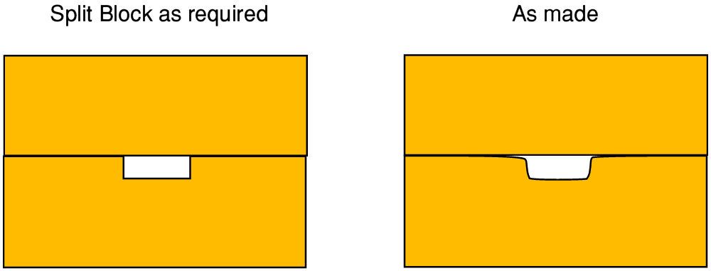
The above illustration shows the kinds of basic problems I encountered from the start with waveguide items made at that time in the mechanical workshop. It shows an end-on view of a ‘split block’ construction. This was the most common method used to manufacture a block with a waveguide which could be used to mount an oscillator diode. Two blocks of metal were made with flat surfaces which could be stacked, one on top of the other. Along one flat face a rectangular groove was cut. As a result, when the two parts were stacked they formed what looked like one split block which had a rectangular channel running though it just under where the flat surfaces joined. For the 100 GHz region a split block with a 2 by 1 mm groove provided the basis of a diode mounting block with a standard 100GHz waveguide.
It was vital that this guide should be a neat, accurate rectangle of exactly the correct width and height and with smooth sides and sharp corners. However what I got when I gave the workshop a drawing for such a block is illustrated on the right, above. The groove had rounded edges and often the top and bottom parts of the block did not meet at flat surfaces at the top of the required rectangle. The result was a waveguide shape that didn’t allow the diode to be mounted in the correct electromagnetic environment. Hence the oscillators when assembled either failed to oscillate at all, or only gave tiny output power levels. Given the irregularities, no two blocks worked the same. This problem happened repeatedly because what was specified on the drawings simply wasn’t what was made.
I recall on one occasion the then-head of the workshop telling me that it was “impossible to make” a specific design like this for an oscillator diode block. This did annoy me and I had to reply that I knew he was wrong, because it was the same design that the QMC mechanical workshop had – more than once – made perfectly from the same drawings and specifications.
I’d seen and used many blocks of this design during the previous years, and so knew he was wrong. The root of the problem seemed to be that the head of the mechanical shop just didn’t really care or take pride in good work. And at the time the other mechanical technicians then would go along with this attitude. The result was that it tended to be taken for granted that work could just be bodged and it didn’t matter. (There was, fortunately, one technician who felt differently, as became clear later on! But I did not realise this during the first year or so.)
My planned research at the time was of two kinds.
1) The National Physical Laboratory (NPL) were paying me to do some research work on what was called “groove guide’. This was of interest to measurement scientists working for the JET (Joint European Torus) project. The NPL were happy to fund me to do the work on groove guide. As a result – outside the teaching periods – I spent some time at the NPL, Teddington, and at JET. On a couple of occasions I spent weeks working at NPL using their equipment to make measurements. At other times they loaned or gifted items to me to work with at St Andrews, and that work brought a small amount money into the University to supplement my basic allocations for equipment and consumables.
2) Developing useful solid-state oscillators for the mm-wave region. When I was at QMC this was specifically directed at better receivers for UKIRT and then JCMT. That continued, in conjunction with Nigel Cronin and Derek Martin. However I started to think in terms of a wider range of possible users and applications for these sources. As a result I decided that satisfactory oscillators could eventually provide a source of income for supporting my research work. However for this to proceed I needed to be able to have someone manufacture working oscillator blocks (the mechanical metal and waveguide arrangements), obtain suitable diodes, and then be able to test the resulting oscillators – using an interferometer.
I still had access to Impatt devices. However it was becoming clear that an alternative type of devices called a Gunn diode was looking like a more promising candidate for developing reliable, high performance, mm-wave oscillators. In particular, an American company, Varian (who also made the klystrons) became a source of commercially available Gunn diodes that looked suitable. However these cost a few hundred pounds per diode, and they had a minimum order amount which was higher, so if I bought I’d have to buy more than one at the same time.
The stumbling block was that this meant I needed the money to buy diodes, and to be able to make the oscillator blocks and the interferometer. Ideally, the Physics department workshop should have been capable of making the blocks and the interferometer at a low cost I could afford. Certainly, the QMC workshop had already routinely done such work. But the St Andrews Physics workshop seemed totally incapable of matching that. In theory, I could employ an external workshop to make what I required, but that would cost more money than I had!
The result was a ‘chicken and egg’ problem where I could not pay for the things I needed to make the things which would have paid for them... Fortunately, the NPL/JET were quite willing to pay for me to work on their requirements, and that did bring in some money as the money went into my departmental account, not taken by me as wages. As a result most of my academic work time during my first couple of years at St Andrews was devoted to teaching and to the “groove guide” studies. This brought in some money which could be used to – slowly – move forwards the work on oscillators.
A large part of the JET project concerned plasma ‘diagnostics’. i.e. equipment developed to measure the behaviour of the plasma being created in the torus to allow researchers to gain insight into how it behaved. Alan Costley and others were producing and using mm-wave interferometers and other systems to carry out these measurements. However those instruments and the people using them had – for safety reasons – to be located well away from the actual torus. This mean the mm-wave signals had to be carried long distances, over routes that were not straight lines.
|
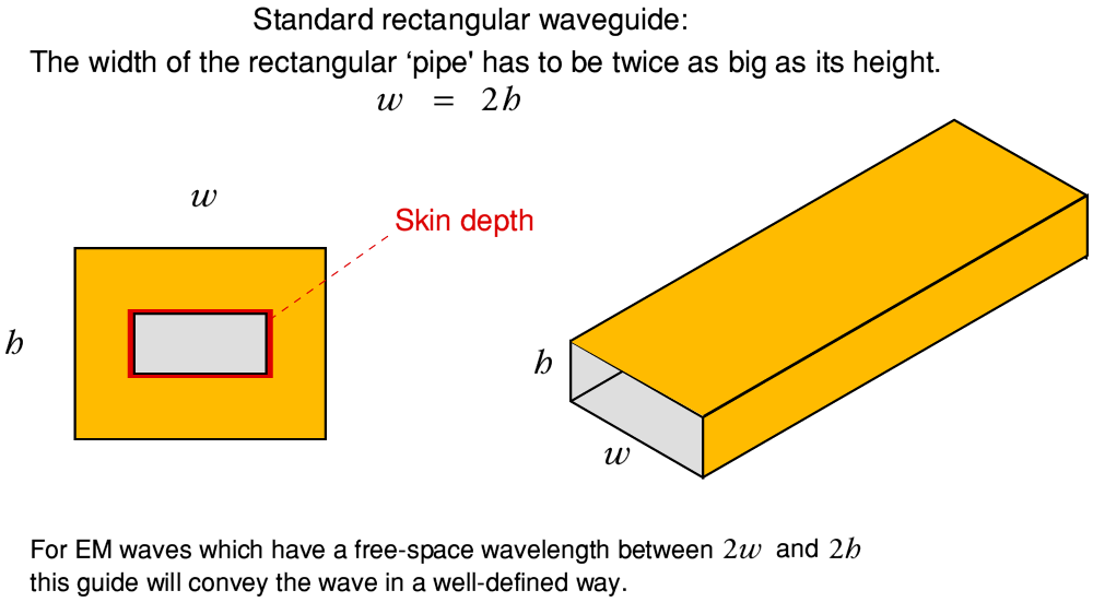
In many lab experiments people would use ‘standard rectangular waveguide’ to carry microwave or mm-wave signals from place to place. This essentially consists of a metal ‘pipe’ with a rectangular cross-section as illustrated above. At frequencies of a few tens of GHz this works very well. As a result, a standardised set of waveguide sizes had been widely adopted by microwave engineers. The main advantage of the standard guide was that the way EM waves propagated along the guide was well defined and controlled provided you follow one simple rule. This is that the EM wave has to have a free-space wavelength which is within a range set by the width and height of the guide.
For operation at frequencies around 100 GHz the usual choice was a guide which had a width, w, of 2mm and a height, h, of 1 mm. The table below shows the standard series of guides adopted for the regions from about 40 to 220 GHz. Similar standard sizes were defined for higher and lower frequencies. You can see that each guide only covered a limited range of frequencies. (To confuse matters, different companies at the time used differing letters to designate the sizes. When most mm-wave academic researchers referred to “W-band’ they meant the 2 x 1 mm guide for the 90-140 GHz range.)
| Single-Mode Range (GHz) | Dimensions (mm) | UK | USA | Commercial |
| 40 - 60 | 4·8 by 2·3 | WG24 | WR19 | U |
| 50 - 75 | 3·8 by 1·9 | WG25 | WR15 | B/M/V |
| 60 - 90 | 3·1 by 1·6 | WG26 | WR12 | O/A/E |
| 75 - 110 | 2·4 by 1·3 | WG27 | WR10 | W |
| 90 - 140 | 2·0 by 1·0 | WG28 | WR8 | W/N/F |
| 110 - 170 | 1·7 by 0·82 | WG29 | WR8 | B/D |
| 140 - 220 | 1·3 by 0·65 | WG30 | WR5 | A/G |
However, for the JET application, people needed to be able to convey and observe a wide spectrum ranging from around 50 GHz up towards a THz or so! If W-band guide had been chosen to link the measurement instruments to the torus it would have introduced some serious problems.
Firstly, standard guide won’t pass low-frequency signals at all! It has a ‘cut off’ wavelength at twice its width. So any EM signals at frequencies below about 90 GHz would not have been able to get from the Torus to the instruments if WG28 guide had been used. Secondly, at frequencies which are considerably higher than 100 GHz the guide becomes ‘multi-mode’ and this tends to muddle up any time or frequency details in what is transmitted. That meant that using larger guide to allow though low frequencies risked making measurements more difficult at higher frequencies. In practice, standard waveguides of this kind generally only really work well over a limited range of frequencies – far narrower than JET and the NPL needed to cover.
In addition there is another problem with metallic guides of this kind which gets worse as you try to use them at higher and higher frequencies. This can be understood by looking at the ‘skin depth’ I’ve indicated in red in the above diagram. The EM waves are guided by being ‘reflected’ by the internal metal walls of the guide. This confines them to the rectangular pipe, but the reflection process requires electric currents to be induced in the layer of the conducting metal just under the surfaces. Metals like copper have some electrical resistance. Hence this current removes some power from the wave as it propagates. Alas, the higher the frequency, the shallower the ‘skin depth’ to which these currents can penetrate. This means the current has a thinner layer of metal to pass though – hence a higher resistance per length of travel along the guide. To make things worse, the width of the guide’s walls also have to be reduced when we want to use a guide that is suitable for high frequencies. That also reduces the amount of metal which is available to conduct. The result is that as we go to higher frequencies and smaller standard waveguides, the loss per metre rise rapidly.
Even ignoring the difficulties of making very small waveguides accurately, this mean that by the time we get to frequencies above 100 GHz, standard rectangular waveguides lose a lot of the EM signal’s power even when only moving along a few centimetres of waveguide. This is just about tolerable for compact systems where the distances are a few cm. But it means that a standard waveguide run many metres long (as required by JET) would eat almost all the signal before it could travel from the torus to the measurement systems!
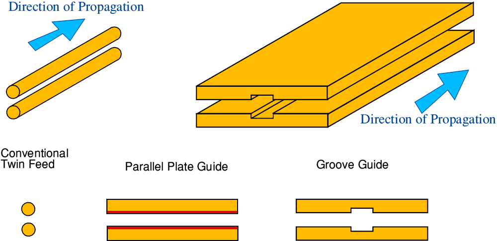
However, alternative types of waveguiding structures did, and do, exist, and one system in particular was of interest to the NPL and JET at the time. This was called ‘Groove Guide’. The diagram below illustrates the basis of the idea behind it.
|
In general, we can use a pair of metal wires to carry electromagnetic signals/power from place to place. Anyone who has ever used battery-powered items like a torch knows this works right down to d.c., so it doesn’t have the ‘low frequency cut-off’ limitation which standard rectangular waveguides exhibit. In the form called ‘Twin Feed’ it is also often used for signals in the frequency range up to a few hundred MHz. So at first glance it looks like a good candidate for a wideband way to carry signals. Unfortunately, it works on the basis that the pair of parallel wires have a diameter and spacing which are very small compared with the shortest signal wavelengths you wish to convey. Go to much higher frequencies and it tends to act more like an antenna and will radiate away the power instead. To push up the range of frequencies it can carry we can, in principle, simply use smaller wires which are held closer together. But this then starts to lead back to the problem of ‘skin depth’ losses because we are reducing the amount of metal available to carry the required currents.
A way to try and dodge that bullet is to change the shape of the conductors. For example we can decide to use a pair of flat parallel plates as the pair of ‘wires’. The above diagram shows in red the width of the metal surfaces which will then be available for the current flow. By choosing wide parallel plates we can produce a much lower level of ‘skin’ resistance (and hence loss) than possible using small wires. Unfortunately, a pair of long plates of metal like this aren’t actually very good at guiding high frequencies. The EM waves tend to diffract and radiate away from the openings at the sides.
Groove Guide tried to play a trick and use diffraction to get the radiated power to keep being drawn back into the central groove, away from the open sides of a parallel plate arrangement. The idea was that, in effect, EM waves propagating along the central part of the guide would find it easier to travel in and around the central ‘groove’, reducing the losses. This did – just – work. But the guiding behaviour was very weak. So the question was, could it be made to work for a long waveguide run that also had to go round some corners as well as carry signals from about 50GHz up to around 1,000 GHz?
During 1984 (and 1985) I spent many days doing theoretical design studies and measurements on Groove Guides, trying to reach a conclusion about this question. And to see if we could find a design that worked satisfactorily. My lab-books for that period contain dozens and dozens of pages of equations, measurements, etc, on this topic. For the JET diagnostics work being done by the NPL it was a very important topic at the time.
As we investigated it became quite clear that getting the Groove Guide to work was a bit like balancing a pencil upright on its tip. If everything was absolutely perfectly right, it could be done. But the slightest imperfection or alteration anywhere caused things to go wrong. However, although we rapidly formed the impression this was the case, the lack of a good alternative at the time meant we persisted just in case the problems could be solved.
During this period I did put in a grant application to the SERC asking for some money to build an interferometer for measurements on oscillators. To my genuine shock they turned this down for a reason that baffled me. They said I had not asked for enough money for it to be worth them bothering to consider the application! No scientific reason was given. It was my first direct experience of just how different the process of assessing research grants was from asking a commercial concern for money for work they’d find useful.
During November 1984 I spent a week or so visiting various locations, looking for support to push forwards my research work. On the 23rd I visited Roger King at EEV, Witham (Essex) to talk about travelling-wave tubes and solid state oscillators for mm-wave uses. In contrast, the following Monday I visited QUAD in Huntingdon to see Peter Walker. I’d met Peter a few times before at Audio Shows, and when he’d visited Armstrong, but up I’d never seen his factory. So I went partly to see him and how they made the Electrostatic speakers, but also partly because I’d been thinking of applying Gaussian Beam Mode analysis to the way the ESL63 speakers radiated sound in a ‘beamed’ manner. It was an enjoyable visit and I came back to London by train along with Ross, his son. The following day I visited QMC and met Derek Martin to discuss how my plans and his might be co-ordinated.
During this period Prof John Cornwell was acting as pro tem head of the St Andrews physics department. I had raised with him the way Stradling’s departure was gutting the support it had been agreed would be provided for my research. So he had been discussing with Tony Stradling what might be left for me, and how to deal with this ‘hole’ I’d been dropped into. On the Wednesday I phoned to ask how these discussions were proceeding. The next day I visited the NPL to discuss the JET-related work with Jim Birch (NPL), and Elizabeth Baker (DTI). I then returned to St Andrews. These visits were helpful, and EEV did provide some support for the work on solid state oscillators. (They also let me have some travelling wave items which, alas, a later research student destroyed.) But as I returned to St Andrews I still faced the problem that I lacked the money to buy a reliable supply of diodes, or to pay for a commercial workshop to make blocks or an interferometer to the required mechanical standards.
Shortly after I got back, I was told that it had been agreed that Tony Stradling would take all his kit away, but I was being allocated about two thousand pounds ‘extra’ to help me deal with the loss. That represented only a small fraction of what I’d have needed to actually fill the gap. And meant delay until I could find a way to get what had previously already been in place. So, better than a poke in the eye with a sharp stick, but not exactly what I’d be promised when I’d accepted the position as lecturer at St Andrews.
Alas, I also rapidly found that St Andrews was very different to QMC in one vital respect. QMC was one of the earliest UK Universities to realise that its research work could have a commercial side. The result was a set of small companies – QMC Instruments, QMC Industrial Research Ltd, etc – which could link research work in the University to commercial developments and devices. When at QMC I had been employed for some of my work though these companies, as were various other people. My work was on mm-wave devices and systems, but other were involved in researching, designing and making all kinds of things from ultrasonic bat detectors to ships’ anchors!
In contrast, St Andrews at that time had almost no experience of handing ‘commercial’ work. Indeed, many in the university were still of the mindset that it was either ‘not allowed’ or somehow below the status of a university to get their hands dirtied by mere commercial activity! Fortunately, this feeling wasn’t universal. In particular I quickly found that Reg Killean and I got on quite well when it came to finding ways to be negotiate though the “not allowed” and “can’t be done” attitude that was depressingly common at the time. However my initial problem remained that I needed to ‘bootstrap’ my research work.
St Andrews University had recently set up a tiny company it called ‘Stardel’ (St Andrews Developments Ltd) as a way to commercialise some parts of the research work. At the time this company was essentially just one person - Maurice Shepherd of the Chemistry dept – in a small office. It had almost no funding or commercial experience. With Reg’s help I did have some talks with Maurice about Stardel coughing up the investment of buying some diodes. The proposal being that I’d then get some working oscillators made and sold at a profit. Thus paying back the cost of the diodes and providing a return for Stardel.
Before I could achieve this I was lead though a dance lasting many months as the University kept making two blocking arguments. Firstly, that it needed some kind of absolute guarantee that the money would be repaid. Secondly, that as a University, it could not make a ‘profit’ of any kind. Despite setting up Stardel, there was still a widespread feeling that ‘commercial’ activity was something a University simply could not be involved with. So to some extent Stardel was at the time a pawn in an ideological battle between different academics. I could be confident that, given diodes and time, we could start selling oscillators and make a return. But commercial start-ups usually can’t ‘guarantee’ they will make a profit in a given (short) timescale. They can only show good reasons to be confident it is likely to happen. Without the support, you can’t find out, and eventually an opportunity will be taken by someone else if you delay too long.
Another difference which caught me out in 1984 was that St Andrews didn’t handle PhD studentship allocations in way I’d anticipated. At QMC these could be allocated to a specific member of academic staff so they could choose a student for a project they wanted to carry out. This ensured that a new staff member was able to get a research student to help their research get off the ground. However the norm at St Andrews was that studentships were awarded by a committee/head of dept to specific students. The student could then choose a supervisor or project. Since my research profile with students during the first year was low, no student expressed an interest. So 1984 came and went without my gaining a research student. Once I realised what was happening I set about arranging to deal with it, but that then had to wait until the next year.
Chris was also facing some worrying difficulties during our first year at St Andrews. She had quit QMC, come with me to St Andrews, and we had married. The assumption we both had was that she’d find a new job in St Andrews once we had arrived. After a number of interviews we realised this was more difficult that we had thought. She was a skilled physics teaching technician, and had gained degree-level qualifications in other areas as well. But it became evident that many employers didn’t want to take on someone who had epilepsy.
At QMC that hadn’t been a problem. Chris had started working there and came to be known and liked before she started having fits. Their only concern was that she was OK. So neither of us had realised the extent to which epilepsy might deter or even alarm potential employers. I was having to work all hours to write my new lecture courses, deliver them, and build my research activity. So she spent long periods alone at home, unhappy with the inability to find an interesting or useful job, despite her qualifications and experience. As a result, the mood swings she had sometimes shown in Leytonstone became more pronounced and she was often very depressed, or uncontrollably angry. Fortunately, she was able to find some unpaid work acting as a volunteer for the local Citizen’s Advice office in St Andrews, and although it was part-time, she discovered that suited her very well.
7600 Words
Jim Lesurf
29th Mar 2018