Time for a change
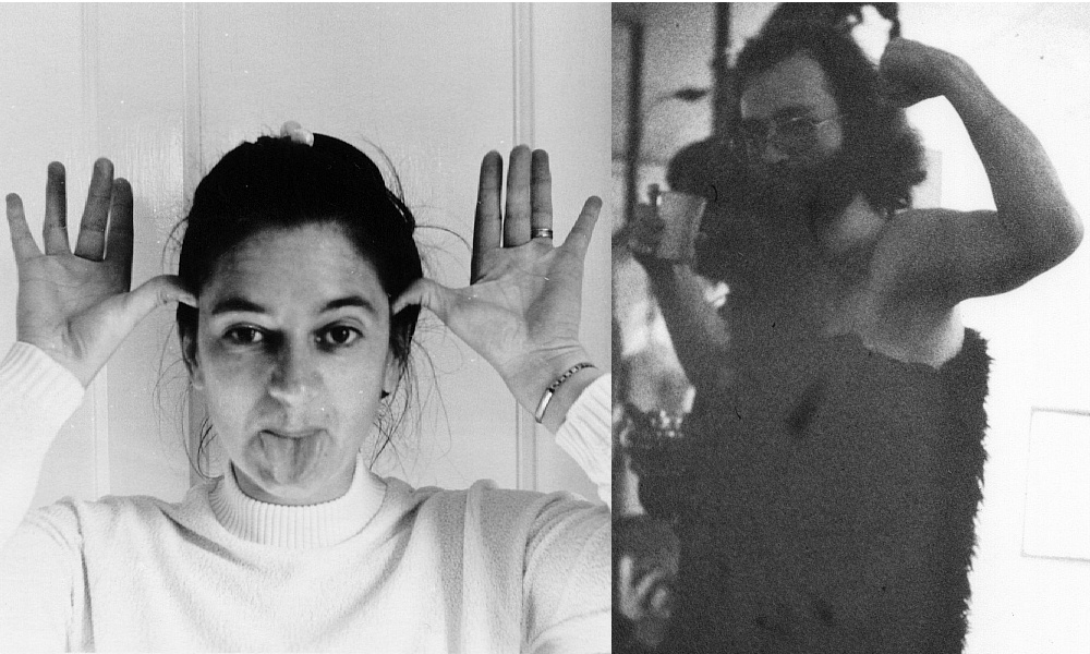
Beauty and the Beast. Photos of Chris and myself in the early 1980s. Hint: I’m the one on the right. The photo of me was taken during a QMC party in Gallery 273 where I’d thought Carey had insisted that she wanted to see more of my bearskin... Chris is demurring in a ladylike manner to my wanting to take her photo.
|
1983 was a year when my life changed significantly. Just a few months before, in November 1982, I’d moved in with Christine Adams. Living as one of a couple was an entirely new experience for me. Chris had been married before, so in principle, was familiar with the situation. But, despite having decided that she wanted to share our lives, she was still haunted by the way her previous marriage had broken up. Although most of the time we got on well, there were days when she became withdrawn or depressed or angry, and didn’t want to have anything to do with me. Still coming to terms with her decision and wondering if it would be a mistake. This did at times distress me, but over the months I realised that her times of doubts and anxiety would dissipate after a few hours, or a couple of days. So, gradually, we learned how to live together as – I assume – most people do while they build such a decision into a reality and come to share good times and bad.
Until the beginning of 1983 I’d been fairly happy to work on the basis of getting one short term research contract after another. The assumption had been that in time I’d find a more permanent position, ideally at QMC. However with the prospect of becoming married I started to feel that I should make more effort to find a more permanent job. I discussed this with Derek Martin, but there was no sign of a lectureship at QMC that I’d be suitable for in the near future. Nigel Cronin had departed for a lectureship at Bath University. So I started to keep an eye on adverts for lectureships at various Universities. If nothing else, I decided that applying for them and being interviewed would help me to practice my skills at presenting myself. While this was going on, though, most of my effort remained directed to the work I was contracted to do at QMC... which had also changed.
The process of developing the initial ‘common user’ millimetre-wave heterodyne receivers for UKIRT had shown that one particular aspect of the original systems was problematic. The optics, and actual detectors worked well, but the local oscillator arrangements weren’t really suitable for a long term user instrument. In particular, the use of klystrons tended to give rise to practical difficulties. They were expensive, had a limited life, and could be a challenge to use and lock. Their requirement for high voltages (over 2 kV) and a water cooling system were added complications. Indeed, a 2kV DC power system was a potentially lethal safety hazard on a large metal telescope frame. Made worse when the user’s ability to think clearly became eroded by altitude, jet-lag, over-work, and lack of sleep!
The overall problem had become obvious to everyone involved. Unfortunately when the initial systems were developed there was no practical alternative to a high voltage ‘beam tube’ of some kind – i.e. a klystron or carcinotron (which required even higher voltages). In contrast, the basic methods developed for the optics and detector/mixers had become well established and worked satisfactorily. So at the start of 1983 my area of interest switched from optics to the process of finding and developing alternative – solid state - local oscillator sources.
Solid state sources for around 100 GHz were just beginning to appear from a few research laboratories during the first few years of the 1980s. These weren’t a routine and reliable item you could buy from a catalogue. But the early developments showed promised that they might become much more reliable, safer and easier to use than the beam tubes. No need for active cooling, and could be powered with just a few volts – typically around 5 to 10 volts rather than the thousands of volts demanded by a klystron. And with the prospect of the kinds of long service lifetimes and reliability we have come to expect from solid state electronics.
With this in mind Derek Martin, Nigel Cronin, and myself arranged that I would now concentrate on developing new solid state oscillators which would operate in the 100GHz region. Nigel would develop new frequency multipliers, working now at Bath University. Together, the oscillators and multipliers should then provide all-solid-state LO systems for frequencies up into the range above 300 GHz.
Two possibly types of solid state oscillator device were regarded as good candidates. The Impatt Diode and the Gunn Diode. The term ‘diode’ is used in each case because the devices have just two terminals, just like a conventional rectifier diode. But their construction and properties are different in detail. At the time Plessey’s laboratories at Towcester were producing some experimental mm-wave Impatt diodes. So we arranged to co-operate with them. They agreed to supply impatt diodes which should provide output at around 100 GHz. Then at QMC and Bath I would test these and see if they could be used to make useful oscillators, feeding back results to Towcester in exchange for more devices.
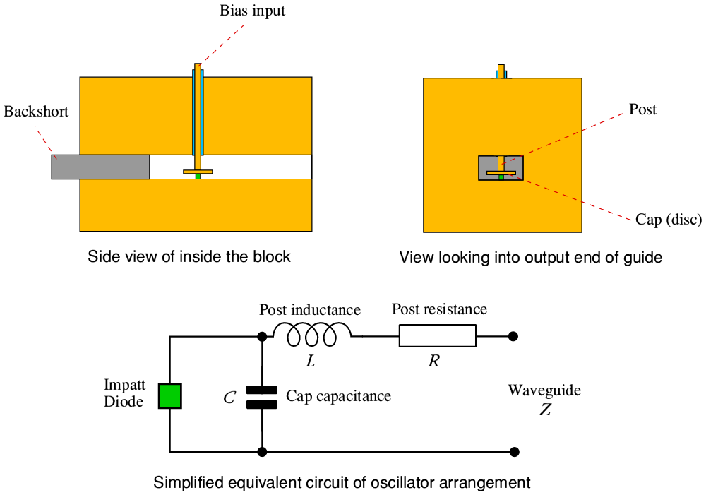
The oscillators were assembled by mounting a suitable diode in ‘W band’ waveguide. The diagram above is a schematic of the arrangement. The cross-section of the waveguide was a 1 x 2 mm rectangle. The diode was contacted using a ‘cap and post’ arrangement. In effect, a thin post was placed across the short dimension of the waveguide to contact the top of the diode assembly. At the end of the post there was a thin circular cap or disc. The behaviour of the arrangement is quite complicated in full detail. But in simple terms it can be regarded as behaving like an LC resonant transformer circuit. Here the inductance, L, is provided by the post along which the current has to flow, creating a surrounding magnetic field – hence the inductance. The capacitance, C, is provided by the electric field between the voltage/charge on the cap and the surrounding waveguide walls. (An alternative model of how the system operates is to treat the cap as being a resonator analogous to something like a cymbal or drumskin. But here I’ll ignore the complications.) The arrangement serves two purposes. It ‘tunes’ the behaviour and – all being well – sets the frequency at which oscillation will occur. It also helps to ‘match’ the diode’s impedance to that of the waveguide. This helps to maximise the amount of oscillation power which can then be extracted.
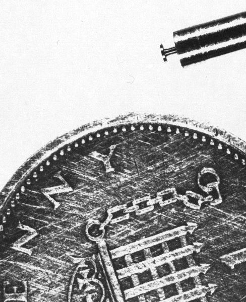
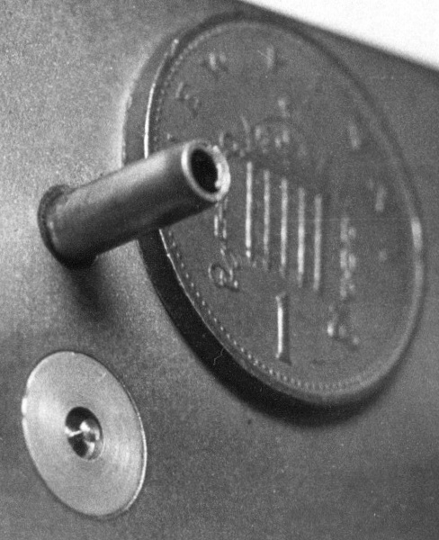
The above photos show an example of a cap-and-post for a basic 100GHz oscillator. These have been turned on a lathe at the end of a small cylindrical rod. The ‘1 New Penny’ coin shows just how tiny the cap and post have to be. The post has to have a very small, uniform diameter. The cap has to be thin and circular with just the right diameter. And all the relevant edges and corners have to be sharp and square to a high level of precision. At the time such items required a very skilled and patient technician to manufacture them, by hand, on a conventional lathe. In practice, although regarded as ‘electronics’ when in use, making a useful oscillator when you had a diode was actually largely a matter of high quality mechanical engineering.
One end of the diode is in electrical contact with the cap-and-post. The other is in contact with the waveguide block. The cap and post is insulated from waveguide block. In the early oscillators this insulation was actually provided by being wrapped in a sheet of thin paper. In fact, paper sold for ‘roll your own’ cigarettes was used! A bias voltage could then be applied between the top of the post and the waveguide block. This would then supply the input power to drive the oscillator.
When the applied voltage was low, the Impatt diode would behave almost like an insulator. Only a low current would be drawn when the voltage was applied. However if the voltage was increased, the few electrons that were able to move though the diode were accelerated by the applied field and given enough energy to knock other electrons free from atoms. These in turn could then be accelerated and knock yet more electrons free. The result was an avalanche process where at a given voltage caused the current to rise rapidly with time.
If that process continued for too long the current density and electrical power dissipation would rise until it overheated the diode – which would then fail. But the circuit arrangement was designed to prevent this. Given the right kind of cap-and-post arrangement the sudden flow of electrons would quickly remove a chunk of charge from the ‘cap’. That meant the voltage on the cap would fall, reducing the voltage across the diode. That then fell to the point where the avalanche process ceased. The result was a ‘burst’ of electrons carrying a chunk of charge across the device. The diodes also included a ‘drift’ region the chunk of charge could fly though. That ensured the charge movement continued for a suitably brief time. i.e. the diode current flowed for a very short time. As this happened, the charge on the cap began to rise again, the moving burst of charge reached the other end of the diode and departed, and a short time later the rising voltage on the cap prompted a repeat of the entire process. In effect, the diode with the cap and post kept switching on and off very quickly. Hence oscillating.
The full details of how the Impatt diode works are complex and involve understanding the electronic properties of semiconductors. But the above indicates that – if the details are right – the applied electronic bias voltage and current will cause the system to oscillate and produce a flow of oscillation power at a given frequency along the output waveguide. Unfortunately, get this wrong and the device may well blow up, instead! If the avalanche wasn’t halted quickly enough, the current level would rise too high for the diode to survive. As a result, the devices could fail in a tiny fraction of a second if the arrangements failed to allow the device to oscillate as intended.
In practice many of the early devices failed as soon as you tried to use them, or shortly afterwards. However others would oscillate quite happily, and typically could be persuaded to output a few thousandths of a Watt at a frequency around 100 GHz. This was just barely enough to provide the LO for a mixer diode, or a multiplier for higher frequencies. So gave the hope that higher powers and better reliability could be obtained by developing the diodes and circuits.
From an electronics/solid state point-of-view the main effort at the time was to try and improve the available mm-wave power output and efficiency (i.e. more power out for less dc bias power in). Plus a need to make devices that were more reliable, with a longer usage life, and ideally with more consistency from one diode to another in terms of behaviour. In order to develop better oscillators I was examining factors like the mm-wave output impedance of the diodes and the stability of their oscillation frequency/power. To do this I needed to try and assess the effective ‘quality factor’ (‘Q’) and resonant frequency of the cap-and-post arrangement when it was being used to couple the diode to the waveguide.
The higher the ‘Q’ of the circuit, the smaller any unwanted fluctuations in output frequency would tend to become. So a high ‘Q’ was desirable for an oscillator that was being run at a fixed frequency. However for any given diode impedance there was a specific ‘Q’ value which would maximise the efficiency with which the output power could be extracted. Getting both of these requirements right depended on the actual diode’s impedance. The snag was that that neither the diode’s impedance at mm-wave frequencies, nor the ‘Q’ of the actual cap-and-posts were well known or measured. So this was the area I began to investigate.
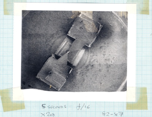
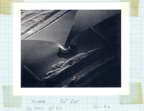
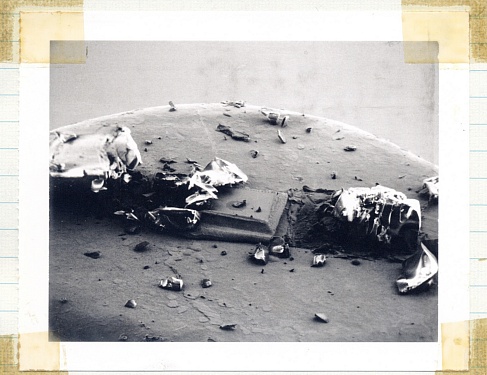
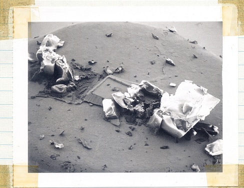
The above electron microscope photos show some examples of the Impatt oscillator devices I was testing. The upper pair of photos show a working device. The lower pair of photos show a device that has, erm, ‘expired’. Diodes which failed tended to vaporise! In effect, they had been struck by (self created) lightning...
The diodes were supplied mounted on the top of a small metal screw. Two 0·1mm cubes of quartz were placed either side of the actual semiconductor diode. A ‘bow tie’ of gold was used to connect the tops of the quartz cubes to the top of the actual diode. This arrangement meant that the pressure applied by the cap and post would be taken by the quartz cubes, and avoided crushing the actual diode. One curio of this form of ‘packaging’ was that the diode and cubes were on what would normally be the ‘head’ of the small screw. i.e. where the usual slot or cross might be to use a screwdriver. Instead, the ‘pointy end’ of the screw had a slot. So in practice you had to screw in the diode by inserting a screwdriver up from below though the tapped hole into which the diode was to be mounted! Given that the diode was tiny, this was a bit of a fiddly process!
Unfortunately, at frequencies above 100 GHz conventional rectangular waveguide like the ‘W band’ type we used tended to have a high loss per centimetre. And the impedance properties of most waveguide equipment was poorly defined as well as varied with frequency. As a result I decided that tests really needed to capitalise on what we had already learned about using mm-wave ‘Quasi Optics’. This allowed more accurate and reliable measurements to be made. looking back at it now, I can see that this was when I began to realise that such optical systems could be used to make ‘circuits’ of arbitrary complexity to serve a wide range of measurement and signal processing functions. In later years this grew to become the main underpinning idea of much of my research and development work.
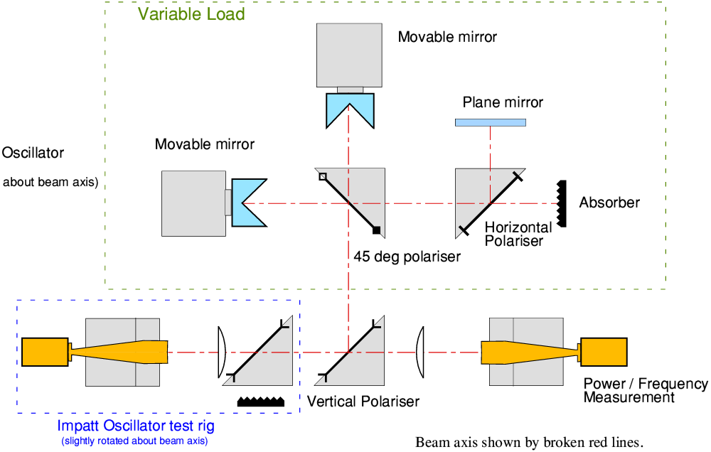
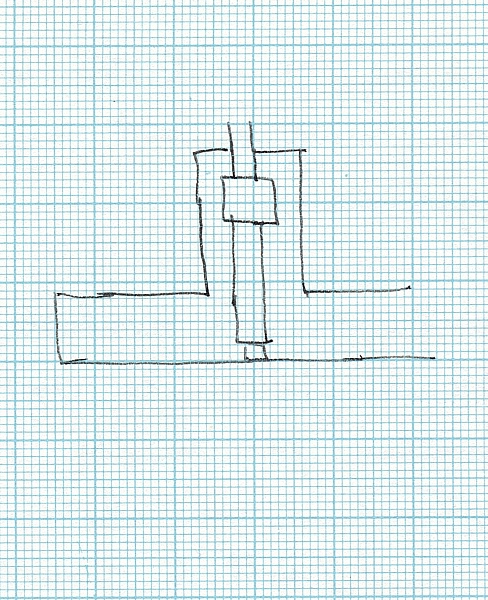
The above ‘circuit diagram’ represents an example of the kind of optical arrangement I used to assess the properties of the oscillators. In effect, it represents a stylised view of a set of components as they might be laid out on a flat horizontal benchtop. Conventional electronics circuit diagrams use a set of symbols for items like transistors, resistors, capacitors, etc. Then use lines drawn between them to indicate how they connect together to operate and perform the required function. The above is similar, but uses a different set of symbols and rules for what can be expected to happen. In both cases the diagram is a sort of language. Once you know the meanings of the ‘words’ and the grammar/syntax of how they fit together you can read the diagram to understand the functioning.
In this specific case the arrangement of mirrors and polarisers at the top of the diagram act as a well defined and precise ‘variable load’. The Impatt oscillator is set up to output mm-wave power with its E-field at a slight angle to the vertical polariser its output is beamed towards. This means that most of that power is then reflected into the variable load. By suitable adjustment of the positions of the two moving mirrors the variable load arrangement can be set to reflect back a well defined amount of this power, setting its amplitude and phase in a controlled way. This mimics the functional behaviour in conventional electronics of being able to add a known and controlled resistance or capacitance or inductance to a circuit to see what effect it has.
In this case, varying the reflection back into the oscillator has the effect of ‘pulling’ the oscillator – changing its frequency and output power level. By measuring how the frequency and power change with the amplitude and phase of the variable load’s reflection we can determine the properties of the oscillator diode and the cap-and-post arrangement. That then helps to know how to modify them to get better performance. In essence this is all a quasi-optical equivalent of similar measurements which can be made at lower frequencies by more conventional means. But at mm-wave frequencies it was able to provide much higher accuracy, etc, than the usual waveguide-based arrangements.
During January 1983 I did some analysis on how this technique could be used, and the maths that would convert the way the frequency/power altered with mirror locations into device impedances, resonant ‘Q’ factors, etc. I then build and used a system to carry out the measurements. In February I took a system and some oscillators to Bath University and spent some time there doing similar measurements with Nigel Cronin. For the best early oscillators the output powers would tend to be in the range up to about 5 mW when optimised. Altering the reflection into them could drive this down to almost zero for some load settings, and others could alter the frequency over a range of typically about 10 to 20 MHz. Given a free-running frequency around 100 GHz this implied effective ‘Q’ factors of the order of 10,000. Quite satisfactory for a device which wasn’t being controlled by an active frequency lock-loop. The main problems were that:
1) They were essentially fixed-frequency devices because the frequency was set by the chosen cap-and-post
2) The devices had a habit of failing in use.
In addition, although adequate for some purposes, an output power of around 5 mW was a bit low for others. So – a reaction beloved of research workers everywhere – “more research and development was clearly needed...”
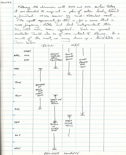
By April 1983 Derek, Nigel, and myself had mapped out a plan of co-ordinated work that would produce a new 115 GHz receiver system by the end of the year. The image on the left shows the version of this plan I wrote in my labbook at the time. Th receiver would include a solid state oscillator I would produce, based on the Plessy Impatts, and a Shottky diode mixer developed by Nigel. Once this was working we might then move on to trying the system with a multiplier, produced by Nigel, and an InSb mixer. The image above on the right is actually from the facing page. It shows a sketch of a ‘coaxial cavity tuned’ oscillator. An approach I would use in later years at St Andrews University.
However by this time I was also regularly looking though the job adverts in New Scientist magazine and various other publications, keeping an eye out for lectureships which I could try applying for. My feeling at the time was that it was likely that I could continue to get a series of fixed-term contracts at QMC and hopefully eventually gain a lectureship there. But this was far from certain, and – if nothing else – applying for other lectureships would help me practice my ability to present myself. It might also serve as a reminder to others that I did want to get a more permanent job.
One particular aspect of the diodes from Plessey was that they felt their Impatts were oscillating with a fundamental frequency around 100 GHz. This implied they were much ‘faster’ diodes than alternatives other labs had been developing. However their measurements of frequency, etc, used standard microwave lab equipment like harmonic comb generators, mixers, and electronic spectrum analysers. As a result they tended to only have a narrow frequency ‘window’ on what was happening. Their frequency measurements had to assume which comb-generator harmonic was being used. And at times their results seemed oddly inconsistent.
At QMC I was able to routinely use a polarising interferometer to carry out wideband spectrum measurements which covered the range from well below 100GHz up to a THz and above. This approach avoided such measurement problems.
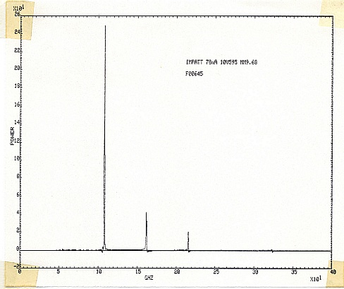
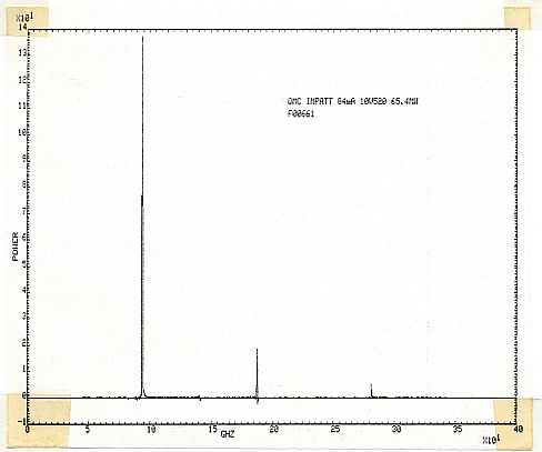
The above pair of graphs shows two fairly typical examples of the resulting spectra I was able to obtain with the QMC interferometer. The example on the right shows a fundamental oscillation at about 95GHz with harmonic output at double and treble that frequency. This is a clear confirmation that in this case the Impatt is oscillating at 95GHz and its nonlinearity is generating the harmonics. Potentially, this harmonic output could be useful as – in principle at least – we can imagine employing a filter to select one of the harmonics for use as the LO for a mixer. This having a device that allowed us to omit any need for a separate harmonic multiplier to drive a mixer at frequencies around 200GHz or above.
The example on the left, however, shows a markedly different pattern of ‘harmonics’. Here it can clearly be seen that these are closer together than the example on the right. Although the lowest frequency component present is at about 110GHz the spectrum tells us that this probably isn’t the fundamental. Instead, it looks like the oscillation is actually at about 55 GHz. This frequency is too low to squeeze its way along the W-band waveguide. So it remains trapped in the region of the diode, cap, and post and we see no sign of power at 55 GHz. What emerges are the harmonics of this 55 GHz (hidden) fundamental oscillation. The overall result showing that although some of the Plessey diodes were oscillating in the 100 GHz region, others were not, despite giving output around 100 GHz! These measurements resolved why some of the results Plessey themselves measured were oddly inconsistent. Something their narrow-window frequency measurement kit of the time was unable to explain.
During the summer I spotted an advertisement in New Scientist magazine for a lectureship in ‘Applicable Optics’ at St Andrews University in Fife. At that time I’d only ever heard of Fife from the text of Shakespeare’s play, ‘Macbeth’! I knew that there was a St Andrews University, but that was about all. However I had in the past spoken about optics and interferometry with Prof Stradling, who was the head of the Physics Department there. Up until that point I’d not actually applied for any of the lectureships I’d seen advertised. I decided that this would make a good ‘first try’ for me. So I sent off a letter with a CV, applying for the job.
In June I got a letter, dated 14th June, inviting me to come to an interview on June 21st. This also invited me to visit the Physics dept. Chris and I took a train from London to St Andrews, arriving the day before. We had booked a room for a few days at one of the hotels on North St. Having checked in we took a walk around the town. It immediately became clear that St Andrews was very different to the Mile End Rd in London! The main roads were largely empty of traffic, and lacked the pollution from all the big lorries that made crossing the Mile End Rd a test of intelligence and the ability to sprint. To the landwards, were green hills. And being on the coast there were some lovely beaches and a view of the sea.
The next day I presented myself at the Physics building and was met by Jim Lawrence, one of the lecturers in the department. He gave me a tour round and introduced me to various people. My actual interview was in the Hebdomedar’s Room in another building in North St, at 4:30pm. My interview went well. During this it was mentioned that the department had another vacancy for a lectureship – this one being in electronics. I was asked if I was also interested in that. I said, yes, and that it would actually fit nicely with my experience and interests.
After the interview I re-joined Chris and we had dinner. We then went to see a film at the Picture House on North St. A particular memory I have of that evening is that it was still daylight when we came out at the end of the film. It was a clear bright evening, so we walked along the beach in the twilight, enjoying the scenery. During this walk I commented that, “This would be a lovely place to work. But I don’t think I’ll be lucky enough to get the job!” It seemed like a magical experience in a far away place quite unlike the real world we had both been used to. We both had fallen in love with St Andrews in a matter of a couple of days. However since it was my first try at being interviewed for a lectureship I assumed its main value would be as practice at applying for jobs.
Having returned we didn’t hear any more. During that time I applied for two other lectureships – one at Imperial College. But I wasn’t successful for either of these. I wasn’t particularly disappointed because I knew that quite often such jobs have to be advertised but in reality they people involved already tend to have an individual in mind. Usually one who already works in the relevant department. However it was giving me practice and letting people know about me.
I’m now not sure of the precise date, but at about the start of August I received an unexpected phone call whilst working in my office at QMC. I was surprised when the caller said he was Tony Stradling, and asked if I’d seen the advert for the Lectureship in Electronics at St Andrews. I replied that I had. He then asked why I’d not applied for the job. I explained that I had assumed that the way I had been asked about the Electronics position during my visit and interview in June meant that visit would be used to consider me for both jobs. Thus, not having heard any more I’d assumed they wished to appoint someone else. Prof Stradling then asked if I was still interested in the Electronics Lectureship, and I said, yes, I was. “In that case,” he said, “I would like to offer you the job.”
I must confess I was amazed that this was happening! However, given that Chris and I were now a couple I explained that I’d need a day or two to talk to her before making a commitment, but yes, provided she was happy to come to St Andrews with me, I’d be delighted to accept the offer. We arranged that I’d phone him back in a day or two to give our decision. Having put the phone down I sat for a while wondering if this were a dream or a joke someone was playing on me. I’d never heard of anyone being phoned up and offered a lectureship they hadn’t actually applied for. Chris and I discussed the offer than evening and she was happy to make the move because we had both liked St Andrews very much. I also spoke to Derek Martin to let him know what was happening. The next day I phoned back and said, “yes”, to the job. An exchange of letters confirming this in writing and sorting out details then took place.
The move required various sorts of issue to be arranged. At QMC the main concern was to continue and finish up the work I was doing on oscillators before handing the remaining work on to Nigel Cronin at Bath University. For Chris and myself the main task was to find and buy a new home in St Andrews, sell the home we had in Leytonstone, and make the actual move. It was also a time of changes at St Andrews because at the start of September 1983 two distinct departments – Physics, and Theoretical Physics – merged to become the new School of Physical Sciences. My lectureship was initially intended to begin on the 1st of September, but because I wanted to finish off my QMC work and give time for moving house, etc, I arranged to start work at St Andrews on the 1st of November 1983. Once that was agreed, I send my formal letter of acceptance on the 8th of September.
At the time Chris was coming towards the end of her Open University degree courses. For one particular examination it had been arranged that she should sit the exam at home. This meant that the OU arranged for an invigilator to bring the paper, oversee the exam, and then take the exam script away for marking. Chris was particularly anxious about this exam. The set time was also whilst I was away for a few days. The invigilator failed to turn up. This upset Chris a great deal, but eventually she took the exam, and duly gained her degree.

Observatory in the garden. The telescope had been up a flight of steps in the dome, supported on the top of a concrete pillar.
|
The process of finding and buying a new home in St Andrews was made relatively easy by two factors. One is that the legal process in Scotland can be much quicker and simpler than in England! The other was that while living with my parents I had managed to save some money with the idea of being able to buy a home at some future point. Chris and I took a couple of trips to St Andrews specifically to look at possible new homes. One almost immediately became our preferred choice. Although quite small, it was detached – useful for someone with an interest in Hi-Fi. The other was that it has a large observatory dome in the back garden. This had been built by a previous owner who was the chief technician of the Astronomy department. Later on he moved to Arizona where the skies were clearer. He took the telescope with him, but left the dome. I was told later on that the pilots flying from Leuchers RAF base used the metal dome as a radar waypoint because it gave a distinct reflection.
We bought the house on a ‘sealed bid’ auction basis. Anyone who wanted to buy had to hand in a sealed envelope containing a letter stating the amount they were willing to pay. The seller’s solicitor opened the envelopes at a preset time, and the sellers could then decide which bid – if any! – they’d accept. At this point, legally, the people who submitted that bit had committed themselves to buying the house for the price they had stated.
The University teaching term started on Monday 10th October. The day specified when bids would be opened was Wednesday the 12th. So I visited St Andrews again from the 10th to the 13th. On the Tuesday I checked that our house bid was in and that the building society was ready to provide our mortgage and hand over the money if we got the house. On Wednesday I visited the School of Physics, spent some time with Reg Killean in the morning and attended my first staff meeting there during afternoon. Reg was one of the lecturers in Physics, and in many ways a kindred spirit. He was involved in building and running the department’s first (Cromemco) computer system. And like myself had an eye towards bringing in research – and money – from commercial sources.
On Thursday I was told we ‘won’ the auction and bought the house. I phone Chris to let her know, then took the train back to London. At this point we still hadn’t sold the house in Leytonstone. Someone had made an offer which we had accepted. But we still had all the processes which feed English lawyers, estate agents, etc, to get though. The prospective buyer then started to try and play mind-games to see if he could force down the price despite having already agreed the amount. My guess is that he knew we had now bought a new home, and he suspected we’d needed a costly bridging loan from a bank. So he assumed we would be paying a lot of money per week in interest until our old home was sold and we had the cash that provided. This kind of game was common at the time. However since I’d saved up some money we hadn’t needed a bridging loan. We were therefore able to reply to him using a phrase involving sex and travel. We made it plain that if he ducked out we’d just find someone else who would buy our old home. So after some foot-shuffling, he bought the house for the price we have already agreed.
The snag was that this process took some weeks. So Chris remained in our old home until it was sold. Most of the furniture, etc, stayed with her during this period. But I moved up to St Andrews during the second week of November 1983 so I could begin working there. On Monday, 7th November I took home a lot of cases and boxes from QMC, and began packing the items I’d be taking. Some items came from my parent’s council flat. I’d left some things there, and my parents also donated a few useful items. In particular an old-fashioned kitchen table and a couple of armchairs. Tony Marston had agreed to drive a large van I’d hired and go with me to help pack and unpack. He was a good friend of us both and this was very helpful. I paid his expenses and for the van hire. For Tony this was also the kind of ‘adventure’ he enjoyed. A chance to drive all the way up the A1 and see St Andrews.
On Friday Tony and I collected the hire van. The next day we packed the van and got ready for the trip. Tony then drove us up on the Sunday, starting off early in the morning and arriving quite late in the evening. I had booked us a night at a St Andrews B&B, but I’d also said that if the trip was taking too long we could stop off partway. However the drive went without a problem and we made the trip in one day. Overnight, we left the van parked outside the house and went to the B&B.
On Monday 14th we shifted the boxes into the house and took the hire van to the company’s Dundee branch to hand over. Tony stayed over that night and went back to London by train on Tuesday. I set about unpacking. I had what, for me, were the vital and/or basic items. One small kitchen table, one swivel chair, two armchairs, a bed, and of course, my hi-fi system, books and LPs, plus my bicycle to get to/from work. I also had the boxes which I could use a side-tables, etc. My first (Radio Communications, Honours course) lecture was on the following Thursday morning.
Chris did come up for visits – e.g. she came and we went to Edinburgh later in November. I also took quick visits down to London, as well as making many phone calls. During one call I mentioned to Chris that I was making a Christmas present for her. She wanted to know what it was and kept asking questions over the phone. But I deliberately gave vague or misleading answers because I wanted the present to be a surprise. At one point Chris asked over the phone, “Is it a computer?” This was because the St Andrews Physics Dept had given me some ‘startup’ money to get some equipment to help my research get going. I’d spent some of this on an Acorn ‘BBC B’ computer and a monitor, printer, etc. I had been saying that I found this very useful for many purposes. And in those days some ‘micro’ computers needed to be assembled or came in kit form. I replied that I wouldn’t tell her what the present was until I gave it to her, but I was having to put various bits together to make it, and “memory” was something the items were known for having.
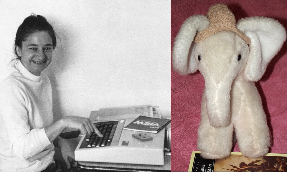 Computers and elephants – both known for having good memories!
|
As a result Chris assumed I’d bought her a computer. At that time she was far from certain she wanted one, and was worried that I was putting a lot of effort into something she might not like or use. However the reality was that in shopping trips around town I had noticed some ‘sew it yourself’ kits to make some soft toy animals of various kinds. Chris has always liked elephants, so I bought the ‘pink elephant’ kit. This came as a set of pieces which you had to stitch together, inside out. Once that was done you inverted it to hide the seams and get the outside, erm, outside, leaving a hole though which you could push in the stuffing. Then sew up the hole and you had a ‘cuddly toy’. So when Chris next came up to St Andrews she was delighted to find not an extra computer but... a pet elephant! A while later on she started using the BBC B I worked on at home, and quickly used it so much that we ended up buying one her of her own. So in the end she had her own computer and a pink elephant.
The process of selling the Leytonstone home was finally completed in early December 1983. We held a homeleaving party there on Monday 5th December. At that point the bulk of our belongings were packed and moved, and Chris joined me in St Andrews. We had emigrated!
Jim Lesurf
6300 Words
4th Mar 2018