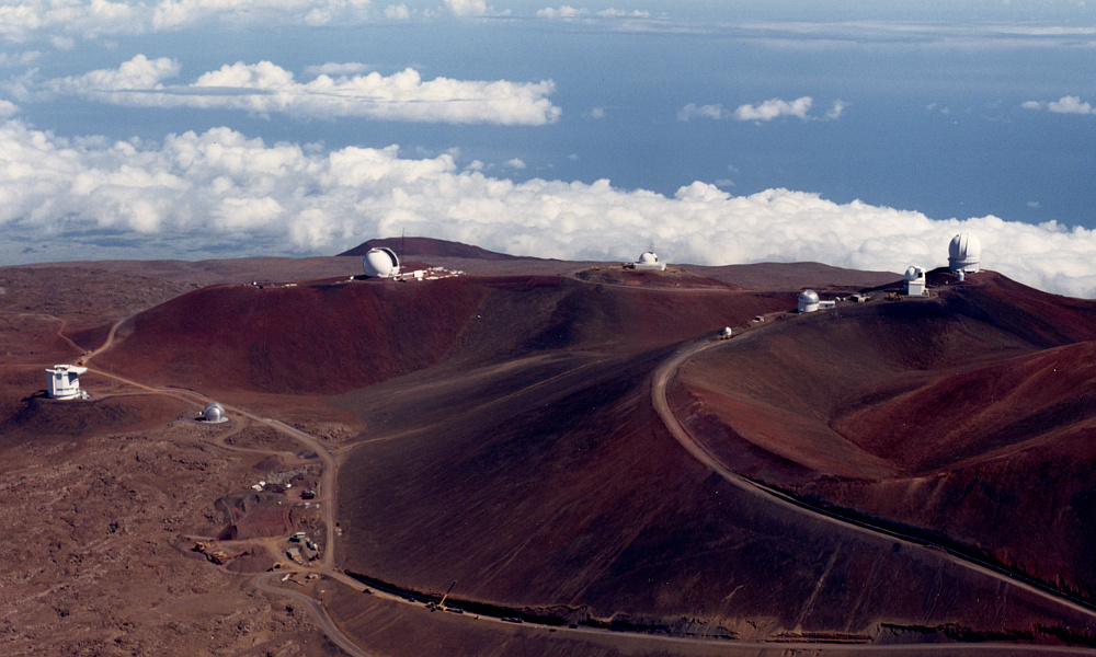
JCMT Sails On!
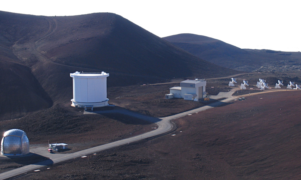
The above photograph shows various telescopes in “mm valley”. JCMT is in the largest building, just to the left of the center of the picture. The CalTech submillimetre telescope is on the far left and the submillimetre array on the right. (ROE photograph taken from the ‘Prospectus’ issued when the UK invited other organisations/countries to take over the JCMT.)
|
During April 1982, Nigel Cronin announced that he had been offered a lectureship at Bath University so would be leaving QMC later in the year. At the time we were looking into making new mm-wave heterodyne receiver systems that might eventually replace the original UKIRT Systems we’d participated in producing. So we discussed with Derek Martin the effects of his move and how receiver work might be shared between Bath and QMC. As this was being done, the expectation was that the use of mm-wave heterodyne receivers would eventually be transferred from UKIRT to JCMT. My QMC contract would run out at the end of the year. So Derek Martin and myself also discussed how how that might be extended and/or other projects undertaken.
During May there was another JCMT progress meeting with Jim Hall (Rutherford Appleton Labs), Richard Hills (Cambridge MRAO), and David Olver (QMC Engineering). This helped to guide decisions like the choice of the diameter for the secondary mirror, etc. It also generated an updated ‘shopping list’ of possibly areas to investigate. For example, the possibility that the telescope could be operated using more than one receiver simultaneously, tuned to different frequencies. Richard suggested seeing if a four-band split, e.g. – below 150 GHz / 220-280 GHz / 330-380 GHz / above 450 GHz – might be feasible.
There was also a rising interest in the possible use of parallel arrays of detectors or mixers. In effect, fairly simple ‘cameras’. By modern standards these would be considered absurdly lacking in ‘pixels’ as the idea was to use a 3-by-3 or 4-by-4 square array, driven using a common LO. Hence quite a lot of scanning would be needed to build up a large map or picture. But when wanting to generate maps/images it had the potential to acquire them almost an order of magnitude faster than using a single detector. So was an attractive idea. And indeed, using larger arrays of detectors became common practice in later years. However at the time making even one mixer or detector that worked well in the mm-wave region was a technical challenge. So in that sense it was an ambitious idea!
The snag was that this meant the optics design had to take into account the desire to use detectors or mixers which are an array where most of them were ‘off axis’. This meant the consequences in terms of the require beam clearances and any changes in antenna behaviour when used off-axis had to be assessed to ensure the final JCMT design would allow satisfactory operation with such an array. An array of detectors would probably also require a larger receiver (e.g. a larger cryostat for a cooled system, so) it would probably have to be located at a Nasmyth focus. Hence the entire optical train from the dome door clearance though to the Nasmyth locations needed to be considered. And – as usual at that time – the calculations had to be done for various possible choices of secondary mirror diameter, etc. Fortunately, analysis showed that the required clearances were feasible without any serious problems arising.
Astronomers who have spent time at the summit of Mauna Kea will be very aware that the weather can vary from glorious at its best to murderous at its worst! John Davies book – The Life Story of an Infrared Telescope – contains accounts of a number of episodes that graphically illustrate this! Around 1980, using the Mauna Kea telescopes could be a bit of a “wild west” experience at times. Bad weather can also be bad news for the telescope and the associated receivers and equipment. And, unfortunately, at visible and near-visible wavelengths it is almost unavoidable that the telescope has to be exposed to its surroundings in order to avoid anything getting in the optical path that would absorb or scatter the wanted radiation. Hence a frustrating tendency for even moderate winds to interrupt observations because of the way they may shake or even damage the telescope. Given that Mauna Kea is generally a dry site, the wind also tends to blow a lot of fine grains of volcanic dust into the air. Again, not good news for precision optical/mechanical system, or the lungs and eyes of people at the telescope!
|
|
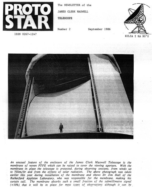
| The membrane featured on the front cover of the September 1986 issue of Protostar. (Photo ROE / Jim Hall)
|
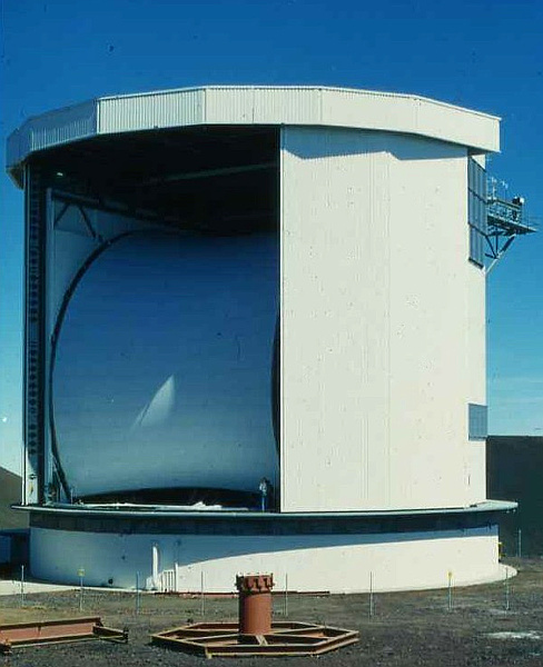
This shows the membrane in its closed position during the construction period. (photo courtesy of Richard Hills)
|
With this in mind, the JCMT developers had decided to investigate the possibility of fitting a curtain or membrane of material across the opening between the dome doors. The aim being that if a suitable material could be found that was effectively transparent in the mm-wave region it could then protect the telescope – and the observers – from the wind, dust, etc. It wasn’t likely to cope with the worst weather. For that the doors would need to be closed, and the people might have to leave. But a membrane could enable safe telescope operation to continue in conditions that otherwise would require observations to be abandoned. Thus it would save a lot of wasted observing time ( = money) and keep observers happy. The challenge was to determine if a suitable material could be found, and what effect it might have on actual observing.
In addition to protection from wind and dust, a membrane also offered some thermal advantages for daytime operations. Sunlight on parts of the telescope could produce alterations in its shape, degrading performance. So the intention was to find a membrane which was transparent for mm-wave radiation but which reflected visible and near visible radiation, shading the telescope from sunlight. This was felt to be a good idea for various reasons. For example, I am aware of an incident at another telescope some years earlier. This was an optical telescope being used for sub-mm observations during the daytime...
By accident the telescope was left unsupervised and sunlight managed to reach the primary mirror. From there it was focussed onto a hot spot striking the inside of the aluminium dome. This proceeded to melt. The result was a scar traced out in the metal as the sun moved, and the dropping liquid metal set fire to a bench! Hence one of the less obvious reasons for having such a membrane was to help protect the telescope and observers from the errors of the observers.
The March 1982 version of the JCMT enclosure specification (MMT-02) suggested that the membrane might consist of either:
-
A single layer of Nylon (Nylon 80), 110 microns thick, coated with Polyurethane.
-
Two layers of Nylon 80, with a 1 metre square quilting structure, peak spacing around 400 mm.
Nylon was available in a suitable form to manufacture the required membrane, and should be reasonably strong and durable. However from the materials measurements carried by Jim Birch (NPL) and myself some time before we already knew that Nylon was a relatively high-loss material. Polyurethane was also a high loss material, but hopefully any coating could be relatively thin to minimise the losses produced.
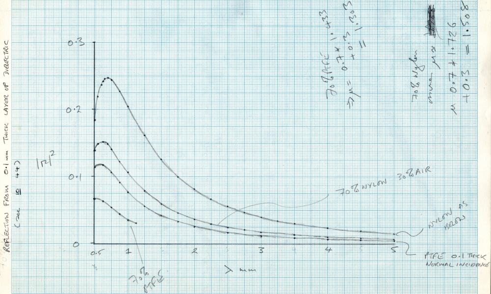
The above graph was taken from my lab-books. It shows the level of power reflectivity for a 0·1 mm thick layer of various types of possible membrane material.
|
The relatively high refractive index of Nylon leads to a high reflectivity in the mm-wave region. It is worth bearing in mind that the reflectivity will also tend to increase for angled incidence. In practice, having a fine woven or mesh membrane helps to reduce the reflectivity because it tends to ‘dilute’ the amount of dielectric material in a 0·1 mm layer. However it might make ensuring the result was dust and water tight more problematic, as well as potentially adding patterns of phase delay variations into the transmitted signals.
Based on the measurements Jim Birch and I had made, Nylon had two drawbacks. One was its relatively high absorption loss per metre, The other was that its high refractive index would tend to cause it to reflect quite a noticeable proportion of the mm-wave signals. Nylon has a typical refractive index in the mm-wave region around 1·72 in the mm-wave region. HDPE has a lower refractive index and a very low level of attenuation due to absorption, so would be a better choice in terms of optical performance – hence its adoption for mm-wave lenses! Alas, suitable large sheets of HDPE weren’t available. It was normally supplied in the form of blocks, extruded rods, or pellets, and these were used to make lenses. And even given a large thin sheet, it was felt that it probably would lack the strength to survive the wind forces, etc, which it would be subjected to for the JCMT application.
Although it might seem an odd coincidence, a clue to the solution actually travelled with me most days as commuted between home and OMC. At that time I tended to cycle around quite a lot. A number of other people working in Derek Martin’s group also cycled. (At one point we even had the college’s safety officer complain that all our bikes were cluttering up the corridor!)
And I’d started using a bike to get around. This was partly a result of seeing the others do so. But it also arose from my weekend trips to East Grinstead to work on the Armstrong 700 amplifiers. Barry and Celia Hope often used to go cycling around on Sunday mornings. I’d started joining in, and that led to me also cycling around in London.
Frankly, in some ways this was probably madness. My most direct cycle route from Forest Gate to/from QMC was essentially along the track of the A11, though Stratford Broadway and over the Bow flyover! Along the way various drivers experimented with ways to kill me. As a result it was a case of “the quick and the dead” even when cycling in a defensive way. Because of this I gradually tended to use longer routes down side roads. This took longer but was less risky, and also was interesting as a way of exploring London byways.
I had quickly discovered that the best cycling jackets I could find were made using ‘Gore-Tex’. This is woven from PTFE thread. For a cyclist it combines two advantages over the traditional materials. It allows vapour and gases to pass though it. So when cycling hard in hot weather you don’t end up sticky and wet with sweat that can’t escape. Yet liquid water won’t ‘wet’ the PTFE cloth. So when it is raining the water runs off you, and you don’t get soaked. I already knew that PTFE is quite strong. Also that it has a lower refractive index and is much less absorbing at mm-wave frequencies than Nylon. If it had been as easy to machine as HDPE it might well have also been the first choice for the mm-wave lenses in systems like the UKIRT Receiver A/B optics.
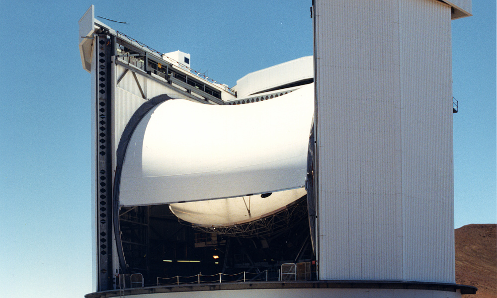
The above shows the JCMT membrane partly raised. You can also see how the side panels inside the carousel dome will combine with the closed membrane to keep out the wind, dust, etc. (ROE 8911402)
|
A similar woven material was also used for sails. In that application it had already demonstrated its strength, that water would simply run off it, and that it wasn’t degraded by exposure to water or bright sunlight, including UV. (Unlike some polymers which gradually get broken down by UV.) Given its known properties as a bulk material it clearly merited investigation, and the results of tests eventually led to a form of woven PTFE sailcloth being chosen for JCMT’s protective membrane. This was sufficiently transparent and durable that it could be used for mm-wave observations with little or no impact on the results.
Once in operation it wasa found that the membrane allowed observations to proceed even when the external wind velocities were peaking up to around 70 - 80 km/h. In contrast: when the membrane was lowered, wind velocities above only about 20 km/h would shake the telescope enough to upset the pointing accuracy, etc. So the membrane came to represent a major element in the telescope’s usefulness. Many astronomers went home happy with data they would otherwise have been unable to collect because the membrane allowed them to work unhindered by the wind velocity outside. It also made the working environment less harsh.
|
|
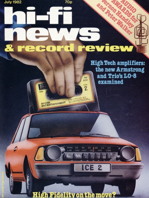
| Cover of July 1982 HFN
|
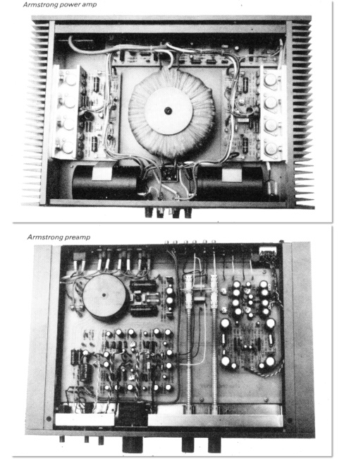
Circuit photos from review
|
In June 1982 “Hi-Fi News” published the first magazine review of the Armstrong 700 amplifiers. [N.B. As is common for consumer magazines, the cover-date shown is for the next month, July 1982. This practice helps extend to shelf life of issues of a magazine in retail shops. But the issue appeared in June.]
Barry Hope, Alex Grant, and myself had hoped that this would also feature on the cover. But instead, the magazine cover art was for a special focus in the issue on in-car audio. Sadly, the review itself was worse than a disappointment. I have already written a detailed account of this review and the facts behind it. If you are interested in all the gory technical details you can find them on the page at http://www.audiomisc.co.uk/Armstrong/reviews/finale/1982.html so here I will just outline what happened...
The review – and a follow-up article which it prompted – contained statements which might most politely be said to such as to be ‘easily misunderstood’ by readers. The sad reality was that magazine reviewing of Hi-Fi equipment had changed over the decades. In earlier decades the reviewers tended to be engineers who ‘stuck to the facts’ and would tend to check with the equipment designer or makers the results they obtained. The aim being to be fair and avoid misleading errors or omissions. However by the 1980s their behaviour had changed, as I have documented on other webpages. Some of them now gained a fair amount of their income from acting as ‘consultants’ to do work on designs for some makers, without this being made public. And they had tended to cease checking their magazine review results with makers or designers before publication.
On one level this could be argued to be sensible because it avoided the risk of a maker trying to ‘bully’ a reviewer into writing a good review when it wasn’t justified. But it meant any mistakes by the reviewer got published and presented as ‘fact’. And in conjunction with the same reviewers carrying out pre-release consultancy work, opened up the risk of secret influences. In effect a pressure on makers to pay for such ‘consultancy’ work to ensure that any later review would be a ‘good’ one. After all, if the same person had said in a consultancy that a unit was OK they would then presumable feel obliged to say so in a later review. If they spotted a real problem, or made an error, it could be sorted out before the equipment went on sale or was reviewed. Against this, it also opened up a human behaviour risk that reviewer/consultants might become predisposed to feel that designs made by firms they had a regular consultancy with would be good. Thus the situation had become quite a strange one by the early 1980s.
Whatever the background might be in the specific case of the Armstrong 700 amplifiers, the review contained a number of statements which puzzled me, and angered Barry and Alex. To the point that Alex did seriously threaten taking legal action against the magazine or reviewer for damages. I can example this here by just two points.
Firstly, at one point in the review when testing the ability of the amplifier to ‘drive’ various kinds of loudspeaker/test load, the reviewer wrote: “...power delivery at the frequency extremes was very good, the amplifier making a close attempt at 400W/channel 4 ohms, both channels driven. The cruel 8 ohms + 2 microfarad 20 kHz was sustained long enough for a fine measured 22 dBW, but then resulted in the amp’s demise.”What concerned us was that readers would take this as a warning that the amplifier had broken down and would need repair. As a result, they would be reluctant to buy the amplifier in case it also broke down. The reviewer was unable to say why this “demise” happened, apart from it possibly be due to using this “cruel” load.
However the reality was that I had used exactly the same type of load countless times over many years of developing the amplifier. It had never broken down during such tests. Unfortunately, we didn’t see the review until it was published so I had no chance to try and sort out what had happened before publication. But having seen the review I guessed what had probably happened.
In fact, he had simply blown a fuse in the amplifier’s power supply. From experience (and re-tests when we got the amplifier back) I knew that the fuse would not actually have blown as a result of the “cruel” test. But it would if the reviewer had accidentally shorted-circuited the amplifier’s output whilst it was trying to deliver sustained very high high output levels. When we got the units back some time later I checked, found a fuse had, indeed, blown and replaced it. The unit them worked again perfectly well. Including into the specified “cruel” load.
The curio here is that amplifier reviews other issues of the magazine reported when a fuse blew in such circumstances and it wasn’t regarded as problem. In addition, it is worth pointing out that we had supplied circuit diagrams with the amplifiers, and they showed the fuses quite clearly. The reviewer was an experienced audio engineer /consultant and could read circuit diagrams. And he mentioned in his review that gross overload protection fuses were fitted. But apparently it never even occurred to him to check and see if any had been blown. The result was a statement in the review that was likely to be unfairly damaging to the sales prospects of the amplifiers. For such a sustained extreme test signal that has nothing to do with musical waveforms, to blow a fuse isn’t actually surprising. Indeed, if the same output waveform had been applied to domestic Hi-Fi loudspeakers it would have destroyed them before it blew the fuse - and might well also have harmed the hearing of anyone listening!
Secondly, the reviewer complained that the overload/clipping level for the ‘moving coil’ preamp was too low. In fact, his measurements disagreed markedly from mine, both before and after the review. In addition he compared this part of the 700 amplifier with another well-regarded moving coil preamp which he pronounced as being clearly superior. In another context this pronouncement would have actually been hilarious. The design of the 700 amplifier’s moving coil section was actually based on this alternative which he felt better. And the only changes were minor ones that increased the amount of input required to overload it! Thus his comments might most politely be described as, erm, ‘misguided’.
If the reviewer had spoken with me beforehand I would have had a chance to point out some relevant facts and the printed review might have been different. The difficulty is that most readers of the magazines would not have been experts in the design of amplifiers, they just wanted to buy reliable equipment that performed well. And the specific details of the circuits involved were not published, so they had no evidence to form a view of their own contrary to that of the reviewer. Those readers who did have some electronic engineering background would probably have taken for granted that if the unit stopped working the reviewer would have checked to see if a fuse had blown. And, indeed, might have contacted the maker to check in case something was wrong.
Eventually Alex calmed down and decided it would be a waste of time, money, and worry to take any legal action. There was a follow-up item in the magazine which actually settled nothing. Overall, it was perhaps a lesson which many other designers may have encountered over the years. I have wondered how many new products didn’t sell because of similar problems in what was published in a review. Since my main work by this time was back in University research I concluded that Hi-Fi had largely become like the ‘high fashion’ trade. I decided that a University career made more sense despite my continuing interest in high quality audio and music. So, personally, I probably didn’t lose out. My main concern was the disappointment for Alex and Barry. In fact, decades later I am still happily using Armstrong 700 amps, and I don’t think I’ve ever had a fuse failure in them during 35 years of daily use.
Another review did appear a few months later in the September issue of “Popular Hi-Fi”. This didn’t have the same problems as the Hi Fi News example and thus gave a much better impression of the technical performance of the amplifiers. However it did engage in what are sometimes called ‘wine tasting’ comments on the ‘sound’ of the amplifiers. This remains quite common in Hi-Fi reviews. The snag being that unless you have the same taste in music, the same room, and the same loudspeakers, etc, your preference may be for a different ‘wine’. Assuming, of course, what the reviewer perceived was due to the amplifier rather than something else. So review comments of this type can be a rather shaky basis for making a decision. But you can, at least, decide if you want to discount them because they are subjective to the individual reviewer’s ears, not yours. Sadly, pronouncements of what look like technical ‘facts’ may not give the reader any hint that they should sometimes be treated with similar caution.
During August I did a small amount of analysis and measurements to help work being done by Gong, a Chinese research student being supervised by Derek Martin. Gong’s project at the time was to develop a form of InSb detector that would have an approximately Gaussian single-mode beam pattern over a wide bandwidth. This was another attempt to see if it was possible to get away from the drawbacks of the traditional ‘cone and rattle box’ designs for cooled detectors. The prototype detector was effectively single mode from around 40GHz up to about 140GHz, and employed a strip of dielectric along the center of the guide, supporting the InSb. So had some similarities to the design I had tried the previous year.
Measurements on the antenna pattern (using a simple plane conical feed) and sensitivity were made using a Backward Wave Oscillator (BWO). The wideband sensitivity was estimated by comparing the output from a hand held over the detector’s antenna, with that from a sheet of microwave absorber that had been dipped in liquid nitrogen. The detector worked, but as my notes put it, was “probably 10 times worse than a standard detector” for wideband input. However it was a prototype, so had scope for improvements. The main limitation was that it was only really working well up to about 150 GHz. Thermal input at higher frequencies wasn’t being efficiently coupled into the actual detector element Hence a scaled-down version might have been better for the 300 GHz region.
Gong was problematic as a research student, but not for the usual reasons. Often, the problem a supervisor faces is that a research student initially lacks initiative. Over the years I’ve tended to describe this in terms that also often relate to undergraduates. They defy the academic version of Newton’s Laws of Motion. You can set an undergrad off on a course of study, only to find they drift to a halt when you stop pushing. Momentum is not conserved! Postdoctoral researchers by contrast should accelerate away on their own initiative. Often postrgraduates start off needing the supervisor to keep pushing, but all being well, soon acquire their own momentum and start to develop their ability to accelerate or move on their own initiative in fruitful directions.
Gong was under a lot of pressure. At the time China wasn’t as wealthy as now. So he was well aware that his state funding to come to study in the UK was a costly privilege. As a result he was eager to learn as much as he could, as fast as possible. In itself, fine and praiseworthy. Alas, it meant he also tended to do things like carry out liquid Helium transfers into detector cryostats when no-one else was around. Helium transfers are potentially dangerous and can lead to an explosion if something goes wrong. So the rule was that two people must be present, and at least one had to be experienced in the procedures. Gong would tend to come in early, stay late, and do whatever he felt necessary to keep working, even when alone. Thus there were times when he caused various headaches. However he did it for understandable reasons and was keen and able.
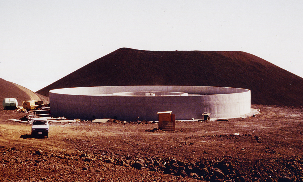
The above photo shows the foundation and base for JCMT at a time during construction before the carousel, etc, were added. Essentially everything built on top of this above this would rotate with the telescope.
|
JCMT was unusual in that all the upper parts of the building revolved as a single unit along with the telescope. i.e. the dome, telescope, etc, all moved together. The upper parts which rotated were known as the ‘carousel’ for this reason.This behaviour could be quite confusing for observers who would emerge after hours of work only to find the scenery had changed! And in the earliest periods of telescope testing the movements could sometimes lack smoothness and induce a feeling akin to seasickness!
On 27th August there was another JCMT project meeting to discuss progress and decide what was required over the next few months. Various areas of investigation were discussed. One was to determine the lowest frequency at which operation would be possible given the then-planned secondary size, clearances, etc. As before, this had to take into account possible off-axis use for detectors which formed part of an array. At this point it had become assumed that only one layer of woven PTFE would be required for the membrane. But details like the thickness, weave, or the possible addition of a coating had not been resolved. Measurement that had already been made indicated that having a coating on the membrane tended to produce a higher level of attenuation loss at high frequencies – i.e. above about 300 GHz. And given that the membrane would be curved, the effect of angle of incidence needed to be checked, along with finding out if this affected the polarisation behaviour to a significant degree.
During September I started working on the use of solid-state devices as alternative Local Oscillator sources. Over the following months as the JCMT optics design became more settled and the optical analysis and design more settled, the proportion of my time devoted to solid state oscillators increased. This work was also co-ordinated with Nigel Cronin after he had moved to Bath University because he had developed the multipliers that allow sources at frequencies around 100 GHz to provide LO for heterodyne mixers at higher frequencies. I also looked into the idea of using the central ‘shadow’ of a Cassegrain arrangement as a possible way to inject LO into a mixer optically. The idea was to use this with an InSb mixer system which only required small levels of LO power at high signal frequencies.
At first glance this approach could replace the use of a thin semi-reflecting sheet of mylar which Glenn White had routinely used for diplexing the LO with the signal. The low bandwidth of the InSb mixers made selective diplexers like the Martin Pupplet impractical. A mylar sheet worked, but by symmetry. if it reflected some LO into the mixer it also would also divert and lose a similar fraction of the incoming signal.
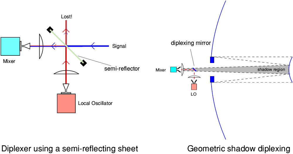 Combining LO with signal for InSb mixers (diplexing).
|
The above diagrams illustrate how the two approaches should work in principle. The diagram on the left shows the use of a thin semi-reflecting sheet placed at an angle in the signal beam from the telescope to the InSb mixer. In practice, this was a sheet of Mylar, attached to a support frame. One useful feature of Mylar is that it is heat-shrinkable. So once it was attached to the frame a hair-dryer or heat gun could be used to tighten it into a plane flat sheet. The thickness was generally chosen to reflect about 5 to 10 percent of incident radiation at the signal/LO frequency. LO could then be directed into the mixer by being reflected off this flat sheet.
The low reflectivity meant that most of the LO power was transmitted though the sheet and thus lost. So for a sheet with 10% reflectivity, 90% of the LO would not reach the mixer! However the amount of LO power required by an InSb mixer was so low that this didn’t normally matter. And the arrangement had the advantage of simplicity. The most obvious drawback was that such a semi-reflecting sheet would also reflect 10% of the signal power out of the beam, so only 90% of the signal would reach the mixer. But this loss was felt low enough to be acceptable.
The ‘shadow diplexing’ idea is illustrated by the above diagram on the right. The trick used here is to try and exploit the way the secondary mirror ‘punches a hole’ at the center of the the incoming signal wavefront arriving from the astronomical object being observed. This ‘casts a shadow’ which is then focussed down the beam which eventually reaches the receiver. The argument then goes that if we put a small ‘diplexing’ mirror in the beam, arranged so that it fits inside this ‘shadow’ region it doesn’t block any of the actual signal power from reaching the mixer. But we can then use this – 100% reflective – mirror to efficiently couple LO power into the mixer. Using schoolbook geometric ray optics this argument then looks like providing an ingenious way to couple all the available signal into the mixer whilst injecting all of the LO power as well. Perfection!
Alas, if you think the above seems too good to be true, you’d be right! As soon as we try to take diffraction into account the argument starts to fall over. As the signal power travels on from having entered past the secondary, the shadow region starts to lose any sharply defined inner edge. This is because of diffraction effects generated by the edge of the secondary. Hence by the time we get near the detector this ‘shadow’ region will actually contain some signal power. The diplexing mirror would get in the way and prevent that power from reaching the mixer. Hence some signal power would be lost if we add such a mirror.
A similar problem may arise when we try to use the diplexing mirror to reflect LO into the mixer. If the beam radiated by the LO source is spread fairly uniformly across the diplexing mirror then the reflected result will be in a reasonably wide beam, and propagate moderately well towards the mixer. But again, that will mean significant diffraction effects will occur due to the edges of the diplexing mirror being well illuminated with LO. On the other hand, if we direct a narrow beam of LO power onto just the central part of the diplexing mirror we can reduce this unwanted edge effect. But we then have a narrow reflected beam, which – as a result of diffraction – tends to diverge rather more than the wider signal beam. Either way, we end up with only a fraction of the LO power being sent to the mixer.
In fact, things are even worse than this for a reasons which schoolbook geometric ray optics can’t deal with. The mm-wave mixers used in the receivers generally operate in a ‘single mode’ way. This means they are fussy about the specific EM field pattern they will accept. As explained on an earlier webpage, using a ‘Scalar’ (Corrugated) Feed Horn and single mode waveguide allows the mixer to operate with Fundamental Mode Gaussian Beams. This optimises various aspects of performance. But it means if you shine radiation into them which has some other shape of EM field pattern they will select only a part of the radiation’s power, and reject (reflect) the rest. This behaviour is founded on the behaviour laid down by Maxwell’s Equations for coherent EM fields. In principle you could, of course, design the mixer to have some other antenna pattern. But whatever pattern you chose, that would be the specific EM field shape it was willing to accept. Shine any other pattern onto it and it will only accept some of the power, reflecting the rest. Maxwell’s Equations aren’t willing to compromise! This is the fundamental snag with the geometric optics idea of using such a ‘shadow’ region to try to get all of two quite different beams into the mixer at the same time. The geometry means you can’t make both of them arrive with the same EM field pattern at the mixer. So something has to give. Hence the idea isn’t as good as it first appeared. There is, after all, no such thing as a free lunch.
The Martin-Pupplet Interferometers (MPI) used as diplexers in the early mm-wave receivers could dodge the above problem. They did this because Shottky diode mixers allowed the use of an LO frequency that was significantly different to the required signal frequency. In the case of the original UKIRT ‘System A’ the LO was set to be about 4 GHz offset from the signal frequency. This allowed the MPI to act in a frequency-selective manner. Both the signal and LO beams could then be designed to arrive at the mixer with the required EM profile. Unfortunately, the InSb mixers required the signal and LO frequencies to be much closer together. Typically differing by a few MHz or so. Making a frequency sensitive diplexer like the MPI for that situation was impractical. Fortunately, the InSb mixers only needed a sniff of LO power to operate, so using a semi-reflecting sheet worked satisfactorily.
The above is a view from the air of JCMT and shows its location relative to UKIRT and other telescopes up on the ridges. (ROE 8911808)
|
My thanks to the Royal Observatory Edinburgh and Richard Hills for many of the photos on this page.
5700 Words
Jim Lesurf
5th Jan 2018