|
Two different approaches to detector/mixer design
|
Mind The Gap.
On the last Wednesday of July 1981 Prince Charles got married. To escape the blanket media coverage I went in to work at QMC and found that Nigel Cronin had done the same. At lunchtime we walked down to the Queen’s Head and discovered they had an all-day license and were providing free food! As a result, we had a long and enjoyable lunch, courtesy of the Royal Wedding.
By the start of August 1981 my Mother had been in bed at home for over three weeks, in a great deal of pain. She had tried getting up, but it was too much for her, so she’d gone back to bed. However she gradually recovered as the month passed. Chris Adams had been away for a couple of weeks participating in an Open University Summer School. But I’d spoken to her over the phone on the last day of July. I also popped over to see Chris Robson in the Chemistry department to give her some batteries of a type she’d said she wanted.
|
|
Two different approaches to detector/mixer design
|
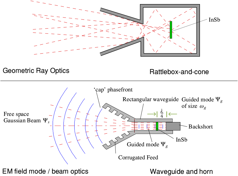
During August I continued to work on a variety of projects. One example was an attempt to devise an alternative approach to the design of detectors and mixers based on cooled Indium Antimonide (InSb). At that point the standard designs were of two general types, illustrated above.
1) “Cone and rattle box” designs were based on a geometric ‘ray optics’ approach similar to that used in many school physics textbooks. A metal cone collected ‘rays’ of radiation which might arrive from a range of directions and direct them into a reflecting metal box. The idea was that the radiation would then ‘rattle around’ until it hit – and was absorbed by – the detecting element.
2) “Feed horn and standard waveguide” designs were based on Electro-Magnetic (EM) wave analysis. The detecting element consisted of a post of material across the center of the waveguide. The waveguide controls/defines the allowed EM wave pattern (mode) which can propagate along the guide. This provides two useful consequences: The field pattern reaching the detecting element is well defined, and by use of a suitable feed horn it also determines the radiation pattern which the system accepts.
Cone and rattle box systems were usually employed for wideband bolometric measurements. Their big advantage was that they were able to work over wide frequency ranges. But the lack of taking into account the wave nature of light and the effects of diffraction, etc, tended to compromise performance at most spot frequencies. And of course, some of the incoming radiation might be lost either by being absorbed by the walls of the rattle box, or by finding its way back out though the cone!
InSb heterodyne mixers tended to use the feed horn and waveguide design. This provides a well defined performance when used with a good telescope. The use of a backshort made it possible to get close to ensuring that all the radiation at the desired signal frequency which was collected by the feed horn would be absorbed by the detector element. Thus maximising the sensitivity. The snag was that a backshort, placed approximately a quarter-wavelength behind the detecting element was required to achieve this, and a side-effect was that it ‘tuned’ the system to that frequency. i.e. As it optimised the sensitivity in one narrow frequency range it also tended to make the sensitivity poorer at some other frequencies. This didn’t matter for InSb mixers because their useful bandwidth at GHz signal frequencies was tiny – typically only of the order of a few MHz. But it ruled out this design when it came to broadband heat detection.
One particular advantage of this approach is that it gives good control over the beam pattern by using a corrugated or ‘scalar’ feed horn of the type I’ve described on another webpage.
|
Behaviour of the Fundamental Gaussian Beam Mode.
|
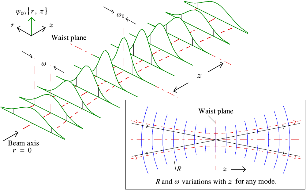
The corrugated feed horn acts as an efficient ‘transformer’ that converts radiation in a free space pure fundamental Gaussian Beam Mode into the field shape that propagates along the waveguide. This level of control over the pattern makes it far easier to optimise the entire optical system because it takes diffraction into account whilst having mathematical simplicity. The above illustrates the behaviour of such a Gaussian Beam.
Ray optics (represented by black lines in the inset part of the above diagram) assumes we can bring the radiation to a theoretical point focus. However in reality the EM wave nature of light means that diffraction will occur and we can’t actually produce a point focus. Gaussian Beam Mode (GBM) optics is based upon Maxwell’s Equations and it takes beam diffraction into account. When we try to focus or transmit a beam of EM radiation, diffraction caused by the radiation having a finite wavelength tends to produce a beam whose width varies in a hyperbolic way along the diection of travel. Thus we get what it called a ‘beam waist’ where the beam width is at a minimum rather than an idealised ‘point focus’.
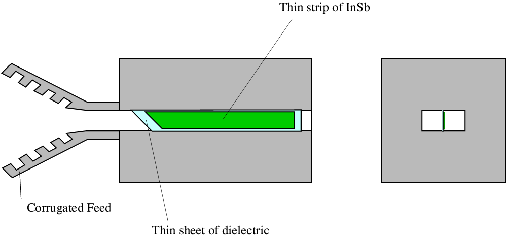
Given this, I wondered if it might be possible to make a wideband detector that was based on standard waveguide, and which could then reliable be used with such a feed horn without needing a backshort that tuned it to a specific narrow frequency range. To do this I looked at possible ways of having a long, thin strip of InSb laid along the length of the waveguide. The idea being that there would only be a very small amount of InSb at each point along the waveguide. As a result the signal would be gradually ‘nibbled away’ as it flowed along the guide, avoiding any abrupt changes that would reflect energy. Given a suitably long stretch of waveguide and InSb – gradually eating the radiation as it propagated – there would be no need for a backshort because almost none of the EM wave would get past the stripe of InSb.
|
Waveguide line detector. |
Any abrupt discontinuities would tend to reflect energy, so the input end of the stretch of InSb needed to be tapered in some way. The InSb also needed to be quite thin to keep the amount absorbed per mm of waveguide fairly low. This meant that it needed to be supported by a suitable piece of a low-loss dielectric.
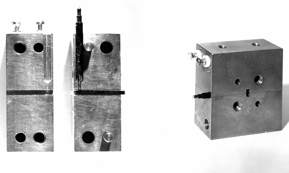
Prototype waveguide wine detector block. |
I did a set of engineering drawings and the QMC technicians fabricated an initial example that used this approach. The photo above gives a general view of what this looked like. Since it was made simply for lab tests the waveguide size chosen was ‘W-band’, so you can estimate the size of the above from knowing that the rectangular waveguide had a nominal cross-sectional size of 1 by 0·5 mm.
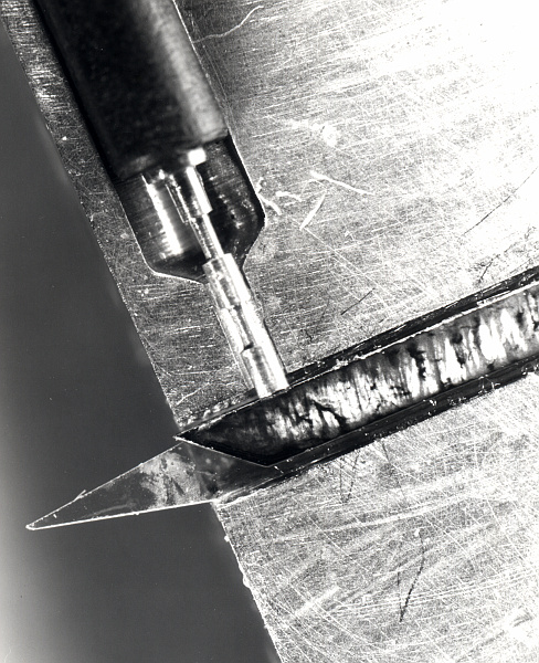
|
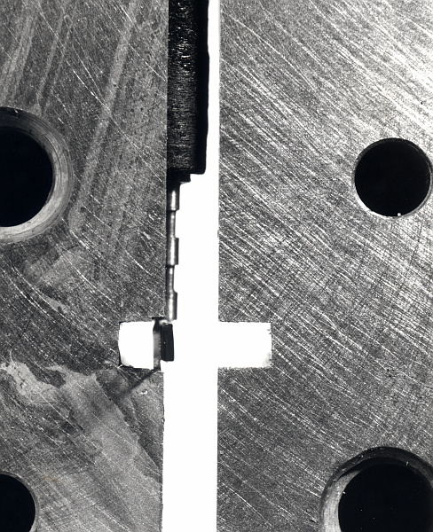
|
The above close-up photos give a clearer idea of the details. The image on the left shows the front electrical contact arrangement and the way the front end of the InSb and quartz support strip were angled to avoid an abrupt transition. Unfortunately, the image on the left shows that one half of the waveguide wasn’t very well machined.
Sadly, the results when tested weren’t very good. I suspect that the main reason for this was that we lacked the ability to get the strip of InSb made thin enough for optimum behaviour. Given more time and money to experiment with making improved versions it may well have come to work well. But I had other things to do. And in practice the established designs worked satisfactorily anyway. The people designing and building them had built up a lot of skill and experience. So they felt no real need to try something rather different. Hence it was one of those ideas that seems neat in theory, but was an unwanted pennyless orphan in practice.
Fortunately, at the same time I was more successful with other projects like designing a ‘Minidiplexer’ for Alan Costley at JET. And my main interest was turning to the work required for what, at the time, tended to be called the ‘MMT’ (MM-wave Telescope) shortening an earlier name of ‘UKMMT’. Eventually, when built and commissioned it was officially titled the James Clerk Maxwell Telescope, or ‘JCMT’. Most astronomers over later decades knew it by that name, so for the sake of clarity I’ll call it JCMT here from now on to avoid confusion.
In practice I started doing some work on JCMT during August, although my formal contract didn’t actually commence until the beginning of the following October. My income during this period came via QMC Instruments. Partly for design work. Partly for making components like wire-grid polarisers.
On Wednesday 2nd September Chris Adams, Karen, and I went to a Prom. Beethoven’s Emperor Concerto with John Lill as the pianist, then Dvorak’s 5th Symphony with the CBSO conducted by Erich Schmid. On the Thursday the 10th Karen and I went to a Prom that was mainly Debussy’s La Mer and and Saint-Saëns Organ Symphony, both of which we enjoyed, and also some works by Boulez, which we didn’t. This performance was by the Orchestra de Paris, conducted by Daniel Barenboim. We came away thinking Barenboim was an excellent conductor, but that Boulez was more interested in formulaic music theories than creating moving music.
The Last Night of the Proms that year was on Saturday 12th September. As usual I’d put my name into the ballot for tickets but got nowhere. So instead, Brad Rose and I arranged for a ‘Last Night Party’ at Brad’s house. I brought along an Armstrong 626 receiver and pair of 602 pre-production speakers. We then set this up to play the Radio 3 broadcast good and loud alongside a TV showing the concert. Much drinking, etc, then took place for most of the concert. Brad handed out crib sheets for the words of Rule Britannia, etc, and we all sang along at the end of the concert.
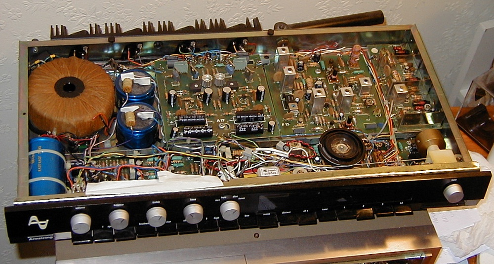
Armstong 626 with the sleeve removed. Good for looks and sound – but not as a beermat! |
The 626’s amp was quite capable of delivering the required sound levels. But I took the wooden sleeve off it because the heatsinks were small. By opening up the box I made it easier for heat to escape without the heatsinks getting too hot. However we had to put the 626 on a shelf up out of the way. Partly so no-one accidentally touched the very hot heatsinks. Partly to avoid anyone trying to stand a drink on top of the 626 and dropping it into the exposed electronics. These days ‘elf-and-safety’ would have had a tantrum!
On Wednesday 16th September Chris Robson and I went out for the last time during her stay in London. We’d arranged to go and see the film “The Four Seasons” written by, and starring, Alan Alda who’d become famous for the “MASH” TV series. We wanted to eat beforehand and Chris took us to look for a particular restaurant she had in mind, but we couldn’t find it. In the end we chose another restaurant at random down a side street. I suspect she chose that particular street to go down because it had a shop with a sign saying “gay stud shop” and she couldn’t resist investigating. So walked down the street and found an Italian restaurant. To my surprise they were playing songs by Stephen Bishop, and went on playing him all the time were were there. A pleasantly romantic backdrop. We ate and had a carafe and a half of wine before deciding we’d never get to the cinema. So we lingered over the meal, and enjoyed the evening far more than if we’d actually got to see the film.
Chris held her “Farewell to London” party in the evening of Friday 25th September at QMC’s Creed Hall out in South Woodford. It was both a happy and very sad event. A couple of dozen people came, plenty to make a good party. Although some who were expected failed to turn up and Ian said he was dissapointed that Anne hadn’t come. There was a lot of beer and wine, so I did my best to help out and drink it! Chris and I danced for the last time and it was an emotional evening because she was always such a good person to be with. I recall once seeing a ‘Peanuts’ card with Snoopy on the cover saying “I like you”. Inside the wording was: “You have the same effect as light on a stained glass window”. When Chris Robson left London, I suspect that everyone there who knew her felt that the light abruptly faded quite noticeably!
I can’t now recall exactly when it happened. But some time during that September I’d been told that Anne Boswell had become pregnant and was leaving QMC. Anne had worked in the Physics dept and had drawn the diagrams for my PhD thesis. Steve Adams had formed a relationship with her as he left Chris. A number of people in the department had signed her leaving/good luck card. Peter Ade of the Astrophysics group had apparently written on the card “Hope it comes out alright!”. She eventually left on the same day as Chris Robson’s farewell party.
A week or two after I’d heard about the card, Chris Adam’s parents took Chris and myself to a see a musical in London, called “They’re playing our tune”. By then I took for granted that Chris knew that Anne was leaving, and why, and mentioned on the leaving card. She was puzzled by what Peter had written until I explained. I then realised that no-one else in the department had mentioned to Chris that Anne was pregnant. The penny then dropped that no-one had been willing to tell her. So I’d ended up being the one who broke the news. The reason Steve gave for having left Chris was that he didn’t want her to be the mother of his children because of her epilepsy. Instead he’d had an affair and then partnered with Anne, leaving Chris. I felt angry with myself because I had taken for granted she’d have known for some time already what had happened. Made me feel like an insensitive idiot and I should have been more tactful.
On Wednesday 30th I received a formal letter from QMC confirming that I would be employed on the JCMT project from the 1st of October. Peter Morse of PCL also asked me if I’d like a lectureship at PCL. This was an interesting offer, and a permanent job, but in the end I decided that I preferred to stay at QMC. I phoned Barrie Hope and he said that he was in the process of making the first batch of twenty production design Armstrong 700 amplifiers at his home. The plan being that once these were made the production process would be transferred to the relatively new premises Armstrong had at Blackhorse Rd in Walthamstow.
During the afternoon I joined a meeting with Keith Marries, Peter Ade, and Glenn White at QMC Instruments to discuss possible items which QMCIRL might be able to sell. I also got a letter from Chris Robson. She was concerned that she might have drunk too much at her leaving party and was anxious that she might have done something embarrassing. But I was happy to write back and let her know that she’d done nothing she need be concerned about and the party had been fine.
Back in the 1970’s mm-wave and Far-Infrared Astronomy was a fairly new form of practical research. Optical and near-optical astronomy had already developed over many centuries. Radio astronomy had largely been spawned in practical terms by work on radar during World War II. As a result, by the middle of the 1970’s there were a number of optical and radio telescopes around the world which astronomers could use, and both fields had become well established. But the mm-wave region was a relatively unknown ‘gap’. During that period mm-wave researchers used to find that other astronomers would ask them, “Is there anything to look at in the mm-wave region?”! In practice, none of the then-existing telescopes had been developed with the mm-wave region of the spectrum in mind. And without having suitable telescopes it was difficult to answer such questions.
The James Clerk Maxwell Telescope. |
Because of these difficulties a number of people interested in mm-wave astronomy had been discussing this situation and try to plan a way forwards. Both in terms of developing improved receiver systems and trying to build a more appropriate telescope which they could use more effectively. This lead to a project to build what eventually became called the James Clerk Maxwell Telescope (JCMT), but in the mid 1970’s was called the UK MM-Wave Telescope. The Project Scientist for this was Richard Hills (Cambridge) working with a group of researchers from various institutions which initially included Tom Phillips and Tony Gillespie who were at QMC at the time.
The two basic practical problems facing them can best be illustrated using a couple of graphs which appeared in what I and others came to call the ‘pink book’, first produced in 1975 by Richard Hills and others. These were the lack of a really suitable telescope for mm-wave observations, and the choice of a suitable site where it could best be located. The first problem could be characterised by a phrase familiar to some London tube-train passengers – “Mind the gap!”
Up to then, observations were done using two different types of telescope: radio telescopes with metal mirrors, and optical telescopes with silvered glass mirrors. The radio telecopes tended to have much higher primary mirror diameters, but a rougher surface than the optical telescopes. None of them had been designed specifically for mm-wave use.
The choice of primary mirror size matters for two reasons. Firstly, the bigger the mirror, the more incoming signal power it can intercept. Hence – give a satisfactory mirror surface – it can allow fainter sources to be observed more quickly. Secondly, a larger mirror should provide a narrower angular resolution of the sky, and thus improve the ability to map or precisely locate astronomical objects. So on that basis, the bigger the better.
The radio telescopes had the advantage when it came to size, but their mirror surfaces weren’t smooth and accurately profiled enough for efficient mm-wave use. These imperfections tend to scatter or diffuse the radiation instead of focussing it perfectly. The silvered glass mirrors used in traditional optical telescopes provided a far smoother and more accurately controlled shape for the reflecting surfaces, but were much smaller.
As a result there was a clear division between the two kinds of telescope in use with neither of them really being satisfactory for mm-wave observations. UKIRT was actually a special case. It was able to employ a particularly large (for the time) silvered glass mirror. The weight being kept down by having a remarkably thin glass primary mirror. This then needed to employ an active system to maintain the primary mirror’s overall shape when tilted. The resulting surface profile wasn’t perhaps then quite good enough for visible-range astronomy, but suitable for Infra-red observing. This also meant it was about the best choice available for mm-wave astronomy... until the JCMT was constructed!
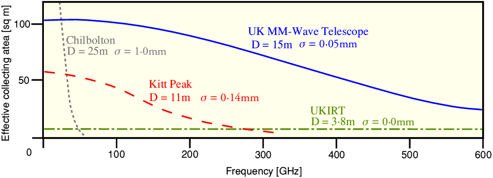
Effective collecting areas of various telescopes. |
The above graph (taken from the ‘pink book’ of 1975) compares the effective collecting areas of various then-existing telescopes with the potential collecting area of the proposed JCMT. Here ‘D’ represents the diameter of the primary and the ‘sigma’ is a measure of the departures from a perfect mirror shape. UKIRT has an excellent surface, but is only 3·8 metres in diameter. The larger diameters of the Kitt Peak and Chilbolton radio telescopes allowed them to collect more radiation at low frequencies. But their larger departures from a perfect mirror profile lead to a loss of efficiency at shorter wavelengths. Not surprising because they were never originally designed to work in the mm-wave range. However given a surface roughness/accuracy of about 50 microns the 15 metre diameter JCMT could work much more efficiently across the whole mm-wave region.
Another aspect of the project was the question of where the telescope was to be located. Since the aim was for it to work at frequencies up into the hundreds of GHz one key problem was atmospheric absorption, which in the mm-wave region is mainly due to water vapour. This is why expeditions had been sent to locations like the Canary Islands during the 1970’s, specifically to measure the atmospheric losses due to water vapour. One example being the trip in 1979 I’ve described on another webpage.
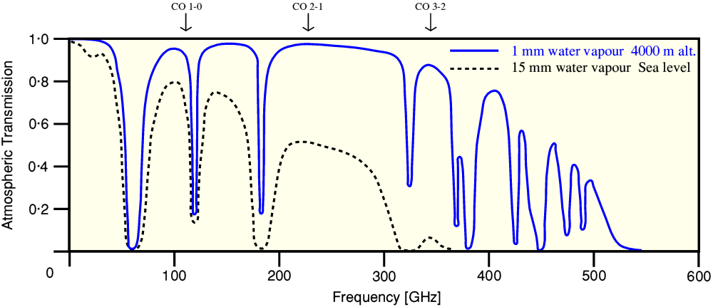
Atmospheric transmission
|
The above graph (again, from the ‘pink book’ of 1975) illustrates this problem. It shows the amount of atmospheric transmission for frequencies in the range up to 600 GHz (0·5 mm wavelength) when looking to the zenith (i.e. vertically upwards). The amount of water vapour present in the atmosphere above the observer is given in terms of imagining that all the vapour were to condense and fall to the ground. This would then produce a layer of liquid water of a given thickness. However in general, most of the water vapour vapour in the atmosphere tends to be in the regions relatively near to sea level. Hence by locating a telescope at high altitude we can get above almost all this vapour and have a clearer ‘window’ to see astronomical sources.
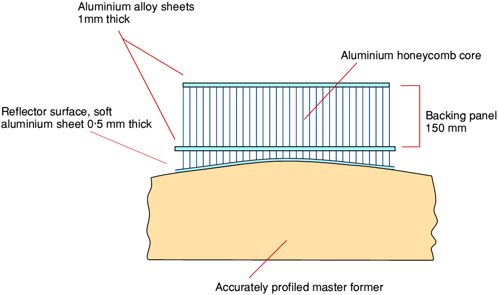
A man with a can! |
The early project documentation shows various diagrams of what the telescope design might look like. The actual design evolved over the years but my personal favourite has always been the ‘man with a can’ drawing which was with the copy of the ‘pink book’ I was given in 1981 when I started work on the project. Later on, I used to use a transparency of this in lectures and talks about JCMT and telescope design. I used to explain that the man shown bottom-left had been included to indicate the scale, but the curio was that he was wearing a white coat and carrying an oil can. The implication being that whoever did the drawing wanted to make clear it was a technician or engineer, not an astronomer. I could then only speculate on why this was done. The two possible reasons which occurred to me were:
1) It implied an assumption that a mere engineer/technician would not be as tall as an academic or astronomer, and this needed to be taken into account when using them for scaling the size of the telescope!
or
2) Whoever made the drawing was hinting that it might not be safe to let actual astronomers do anything on the telescope as they have a tendency to break things and fall over in the dark. So any work on the telescope itself was best left to those qualified to wear a white coat and carry an oil can – i.e. an engineer or technician!
Personally, from experience the second idea made more sense to me, but I never did find out the real intention...
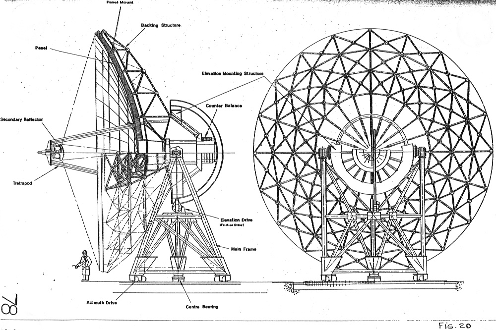
Perhaps the biggest problem facing the telescope designers was due to the need to be able to tilt the telescope without gravity tending to pull the mirrors hopelessly out of shape. Traditionally, this problem had usually been dealt with by designing very rigid structures – which as a result tended to be very heavy and expensive. UKIRT had sidestepped this problem by using an ‘active’ adjustment system which altered the distribution of forces holding up the primary mirror, pushing it back into shape when the telescope was tilted. As a result consideration was initially given to employing the same technique for the JCMT. However after some studies a more elegant passive approach was adopted.
Forming the shape of a panel. |
It was impractical to try and make the primary as a single reflecting sheet. So instead it was assembled as a series of panels, each one being shaped into a trapeziodal section of a parabola. The panels were made from aluminium honeycomb material as shown in the diagram above. The rigidity came from two layers of aluminium alloy bonded to a honeycomb to make a stiff, low-weight, ‘backing panel’. The shaped mirror surface was generated by deforming a thinner layer attached to this via another section of honeycomb, then crushing it against a master former. Tests showed this made it possible to make accurate sets of similar panels for the primary mirror. These were both light and sufficiently rigid to make the design practicable.
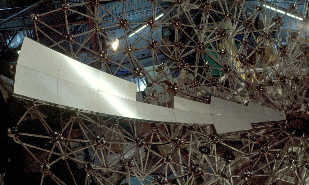
Photo showing some of the panels during the process of telescope construction. |
The overall array of panels was supported by a network behind the mirror, as shown in the above photograph. Rather than try to make this support system rigid, it was designed using an approach described at the time as the “principle of equal softness”. This meant that although the overall system would tend to ‘sag’ in a way that varied when the telescope was tilted, it was designed to occur in a way that was fairly uniform and allowed the mirror to retain the required shape. A behaviour called Homologous deformation.
Once it was established that this could be expected to work well, the early possibility of needing an ‘active’ system like UKIRT’s was abandoned. Despite this, the support system did retain the ability to adjust panel locations in order to be able to correct for changes caused by thermal effects. In the end, the success of these techniques is a testament to the ingenuity of the engineers and scientists who developed the mechanics of the system that was built. As with UKIRT, JCMT employed a lot of ingenuity to overcome problems which in the past had been tackled by a more ‘brute force’ approach of making systems that were simply rigid, heavy, and expensive. The result was a telescope that met or exceeded all its main design goals.
When I joined the project in 1981 the basics of the mechanical design were decided but many of the finer details of the optics remained unresolved. I was asked to help investigate various aspects of the physical dimensions required for parts of the optical paths and equipment. To do this I employed the Gaussian Beam Mode (GBM) methods I’d become familiar with. At the time, radio astronomers tended to deal with questions like these by using number-crunching numerical finite-element computer programs based on discrete Fourier Transforms calculations. In contrast, the GBM approach I’d developed was analytical and allowed me to solve some (awkward) integrals.
Bear in mind that back in the 1970’s even the large mainframe computers used by academics were feeble compared to a modern personal ‘tablet’ or mobile ‘phone’. By the early 1980s the computers had become slightly better and more powerful. But the main advance users had experienced was that we no longer had to submit programs as stacks of punched cards, and wait until the next day to get the results! Also the amount of computer time on the machines most individual users could be allocated was quite limited because so many people wanted to use them.
The standard method which had been developed for analysing the optical behaviour of telescopes and antennas tended to work on the basis of treating the mirror as being made from thousands of small sectional elements. Then numerical calculations were used to laboriously work out the resulting performance in various situations. Because of this it might take many minutes of computer time to get a result like a beam pattern shape or the collecting efficiency of the optics. And if you wanted to make a slight alteration to the optics you then had to re-run the computation all over again. The GBM approach I devised made life a lot easier because I was able to base it on solving some complicated integrals which represented the effect of passing a beam of radiation though an aperture. That, in effect, gave me some tables of values which described how any change would affect the resulting performance of a system.
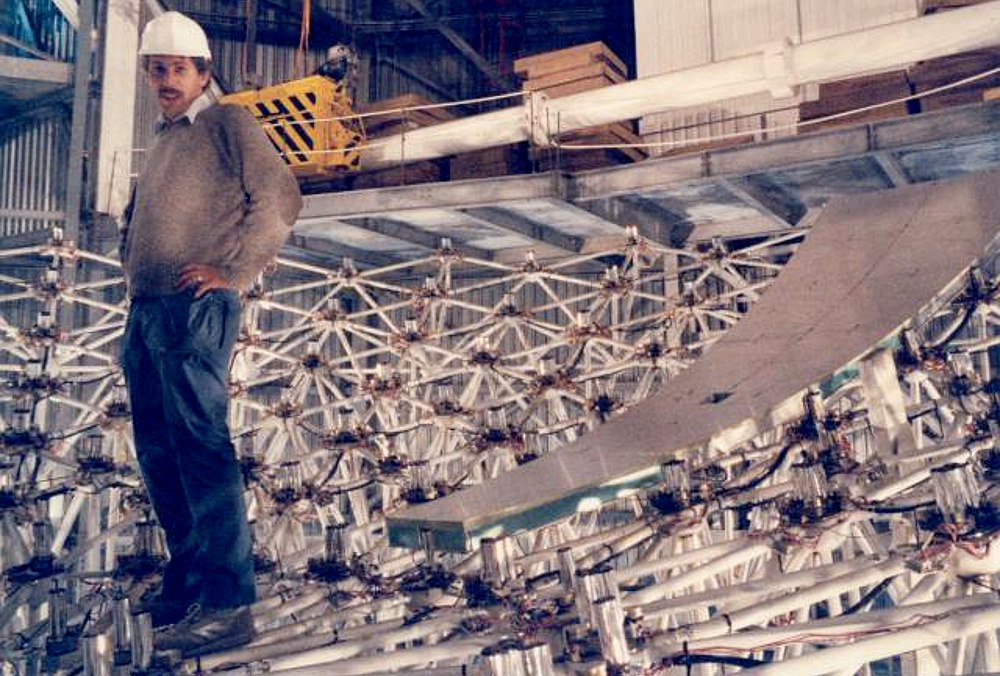
Bill Duncan (ex QMC and ROE) showing that the JCMT panel support structure was quite strong. No oil can, though, so I’ll have to point out he is fairly tall! |
The method is analogous to that used by microwave engineers who may use ‘multi-mode’ guides and transmission lines. A series of GBM ‘free space modes’ can be used to represent the effects of truncation, etc. That then let us analyse the effects of finite mirror sizes, center-blockage by the secondary mirror, etc, etc. Given that mm-wave radiation has a wavelength that is many orders of magnitude larger than visible light, GBM is particularly useful for analysing mm-wave optics.
Although my work at QMC was based on being in Derek Martin’s “Engineering Physics Group” there was also an excellent research group in the QMC Engineering department who were involved with the project. This was run by Clarricoats and Olver, and they occasionally ran meetings on various aspects of the behaviour of radio antennas, etc. During one of those meetings I recall some workers from another university reporting their methods for determining the behaviour of Cassegrain-type radio antennas. This took up about 20 mins of mainframe computer time per output set of results, running a FORTRAN routine on a powerful computer. They then had to run a second program to help check the results for numerical errors and to ensure none of the approximations used in the main program had upset the results. Thus it was taking well over half an hour to get a result. At the time I had one of the earliest scientific programmable calculators - the HP41. Using this while sitting in the audience I was able to employ one of the simple GBM methods to work out similar results in less than a minute!
These days, of course, none of this would matter much because modern computers are so fast and so powerful. And the drawback was that I’d had to slog through pages of algebra, etc, to sort out the GBM methods before I could use them. But having done so, it made working on optimising the details of the JCMT optics much faster and easier, and potentially more accurate, than it would otherwise have been.
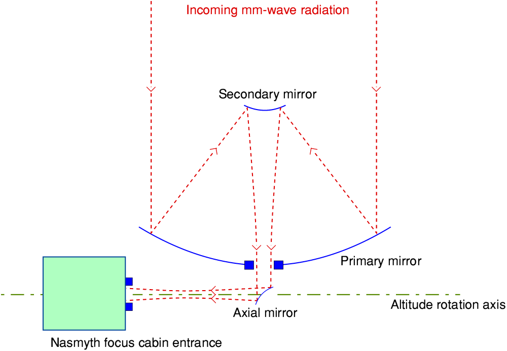
Schematic of Nasmyth focus arrangement. |
The above diagram illustrates one of the first specific topics regarding the optical design that I was asked to investigate. It shows a schematic view of the ‘Nasmyth Focus’ optical chain. In general, amateur astronomers and school physics may describe three types of focal arrangement for reflecting telescopes – Primary, Newtonian, and Cassegrain. The telescope was planned to have a Cassegrain focus, but in addition to this, it was to provide two Nasmyth locations – located at each end of the altitude axis.
The standard Cassegrain arrangement brings the collected radiation though a hole in the middle of the primary and is focussed a short way behind the primary. The JCMT design allowed for this to be used. However the mechanical design uses an altitude-azimuth (‘alt-alz’) mounting. This means the vertical (altitute) angle is adjusted by rotating the telescope about a horizontal axis. The Nasmyth arrangement adds a mirror which turns the beam though ninety degrees and brings it out along this axis.
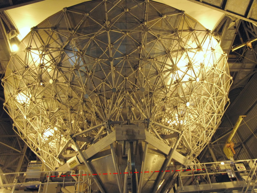
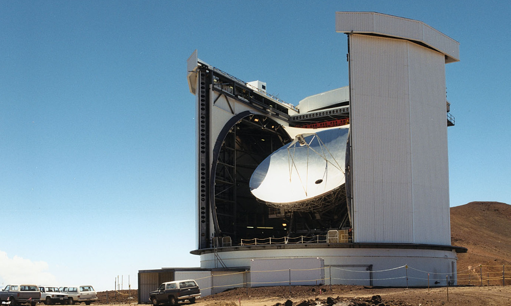
Photo of JCMT showing the altitude (elevation) axis of rotation.
|
The broken red line in the above photo of JCMT indicates the axis about which the telescope is rotated to alter the altitude angle.
By looking at the top of the above photo you can just see the opening between the doors of the building. This indicates that the photo was taken from a point of view where rotation about this axis would tilt the bowl away or towards the viewer. The platforms with guardrails at the bottom left and right are where receiver systems can be mounted at the two alternative Nasmyth focus locations. The advantage of this arrangement is that the receiver systems can be large without weighing down or unbalancing the primary/secondary mirror. In addition a receiver on a Nasmyth platform does not need to be tilted in use. This avoids some practical problems – for example the difficulties of having to tilt large cryostats filled with liquid Helium.
In terms of GBM analysis the Nasmyth optical arrangement consists of a series of elements
The overall result is therefore affected by a cascade of effects due to the various optical elements of the system. GBM provided a way to treat this almost like a standard multi-mode waveguide problem. Although the maths involved was more complicated, an essentially analytical calculation could be done.
The trick was, however akin to the old story of the plumber and his hammer. When called to fix a problem the plumber examined the plumbing for a few minutes and got out a hammer. He then hit a section of the plumbing and the problem was fixed. Then he handed over his bill for 50 pounds and 50 pence. When queried about the cost of a job that had only taken him a short time he amended his bill.
The GBM approach was similar in that some work was required to devise and solve all the relevant integrals, etc. But once this was done the calculations became relatively straightforward.
|
|
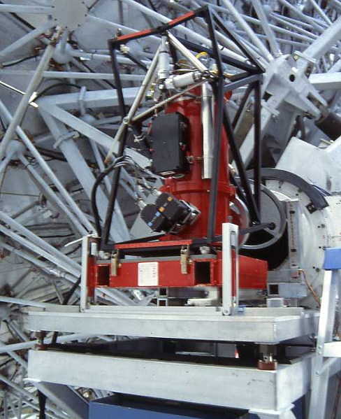
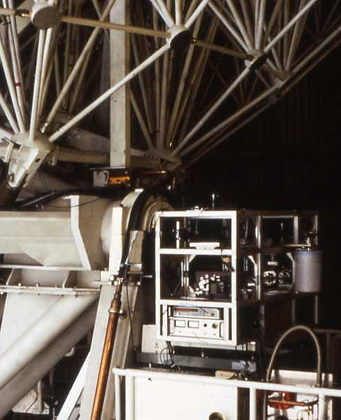
Two different receivers using the Nasmyth focus platforms.
| |
Dave Stone was the Chief Electrical Technician in the QMC Physics dept in 1981. At about half past four on Tuesday 27th October he gave me a letter he’d found in the postgraduate student pigeonholes. Although it was addressed to me it had been put there by mistake. It was from Chris Robson to let me know her viva was at 3pm that day, and that she’d be in the Senior Common Room (SCR) bar afterwards. So I only got the letter in the nick of time! Bill Duncan phoned so I wasn’t able to get to the SCR until 5:25, but I just beat her there. She and Ian had to catch a train at 8:30 from Euston to get home to Preston, so we didn’t have very long, but it was good to see her again. She said she’d be in London again during the first week of December to meet Ian after he returned from his next trip to Hawai’i. So we arranged to meet up again then.
On the 3rd and 4th of November I had meetings with David Olver and Richard Hills to arrange the JCMT topics I should concentrate on during the following months. On the weekend of the 7th and 8th the Physics department had its annual ‘get together’ away weekend at Cumberland Lodge in Windsor Park.
During November Carey decided that the next QMC Panto should be a conflation of “My Fair Lady” and “Pygmalion”. i.e. she wanted to star in it, and fancied performing the ‘good bits’ that she liked from each of them. I was duly tasked to take both – long – scripts and mash them down into a shorter one that suited her whim of iron. However after a couple of weeks of labour on this challenge she changed her mind. So instead we wrote a version of “Snow White and the Seven Dwarfs (aka Seven Research Students)”.
Towards the end of the day on Friday 4th of December I was on the phone at QMC when Chris Robson appeared and we retired to the Senior Common Room Bar for a chat over a drink. During that we arranged to go out the next day to see a film and have a meal. She was back in London for a short time, awaiting Ian’s return from a trip to Hawai’i.
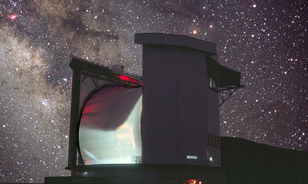
JCMT at night |
The main reason I’ve included the above is that I think it is a stunning photo. However I can find a scientific excuse, ...erm, reason, because it shows the membrane which was used to cover the telescope to keep out dust, etc, when the telescope was in use.
Just before Christmas we performed “Snow White and the Seven Dwarfs”, QMC Physics style. This was the panto I have already described on another page. It included included a stunningly loud explosion, me ‘flashing my baubles’ as narrator / fairy god-something-or-other. and Carey, erm, ahem, slowly eating a banana to much enthusiastic cheering from the audience. As Kenny Everett would have said, it was all in the best possible taste... And I wouldn’t be surprised if even the banana enjoyed it!
My thanks to Ian Robson and Richard Hills for kindly providing most of the photos on this page.