
Jam Tomorrow! |
The Group Expands.

Jam Tomorrow! |
When we moved into our house in St Andrews we ‘inherited’ an excellent garden from the previous owners. A large part of the back garden was planted with various kinds of soft fruit – blackcurrants, strawberries, gooseberries, etc. There was even some rhubarb! In particular there were rows of raspberry and tayberry plants. Of the choice available our preference was for the raspberries and tayberries. Each year during the late 1980s and into the 1990s Chris would go out and pick lots of these, bring them in and clean them. I would then make at least a dozen jars of jam from the harvest. These then lasted us through the next year. Often there was so much fruit that we would let friends come and pick their own, or give them a jar of jam. Blackcurrants were picked and turned into jam that ended up in apple and blackcurrant crumbles. We also discovered that rhubarb and bananas made a lovely crumble. Sadly, I wasn’t able to devote much time to gardening so the variety gradually reduced to just the raspberry and tayberry bushes. I have always been a hopeless gardener. But those bushes seemed very happy on our sloped garden near a fence that helped their location become a suntrap during much of the summer afternoons.
At the start of 1988 the MM-Wave Group had three Ph D students – Graham Smith and Andy Harvey who’d joined in 1985, and Malcolm Robertson who had started in 1987. We also began to gather income from various sources which enabled us to pay for technician time to build the equipment we developed, used, and supplied to others. Initially, Graham’s work was studying and developing improved Gunn oscillators for the 70 - 140 GHz region. However once this had led to reliable high-performance oscillators the group started to use them as a standard building block for our instruments, and to supply to other people. Providing these boosted the group’s reputation and contacts with other research workers. From about 1988 into the early 1990s we tended to build and supply supply around half a dozen Gunn oscillators each year to various companies and research groups.
Andy initially carried out a variety of projects for JET/NPL and then focussed on a specific type of instrument – one which would measure complex impedances – funded by money associated with my being awarded the 1987 NPL Metrology Prize. In order to evaluate the oscillators Graham also had to devise and use experimental measurement systems that allowed him to accurately determine their performance. As a result, he also altered the area of his work from making better Gunn oscillators towards developing improved instrumentation to measure the performance of mm-wave oscillators. In particular, one of the most challenging areas at the time was to accurately measure the Frequency/Phase sideband noise levels of mm-wave oscillators,. (Most simply seen as the frequency stability of their oscillations.) The levels of this form of noise mattered because it could limit the performance of some of the systems in which oscillators would be used. Similarly, knowing the complex impedance of devices helps engineers to optimise their performance in use. Hence Andy and Graham were looking into important areas of measurement where improved methods were needed.
In the second half of 1988 we had been awarded an NPL contract for 3 years to support Andy’s work. EEV Lincoln and the SERC also agreed to fund a new CASE PhD studentship, to start in October. GEC agreed to provide financial support for Graham, as well as supply Gunn and other diodes for him to test. His results helped them to make better diodes, and us to make better oscillators, etc. Involvement with GEC Group companies expanded and we also began working with MEDL (Marconi Electronic Devices Ltd) and the GEC Hirst main research labs on projects to study various types of mm-wave device, etc. In October 1988 I also visited Martin Chamberlain at Nottingham University. They also had access to machinery which could be used to manufacture semiconductor devices. So we began the process of putting together a join grant application to work on devices suitable for use in the mm-wave range.
In November 1988 I placed advertisements into New Scientist magazine and The Daily Telegraph newspaper, inviting applications for the new studentship. By the end of the year I’d received some applications and had sent some replies. One application in particular stood out, so I looked forwards to having one more person join the group during 1989. In reality, though, it turned out that three new PhD students joined the group during 1989...
During the last few years of the 1980s and into the 1990s my main research interests tended to be directed to developing improved instruments and better solid state local oscillators for the millimetre-wave region. The Institute of Physics (IoP) had also contacted me having seen the article I’d written for ‘New Scientist’ magazine in 1988. They’d suggested that I should write a textbook for them on mm-wave and ‘Quasi Optical’ (QO) methods. So I had begun to think about this in a more systematic way.
In general, people making laboratory measurements in the 100GHz region had tended to use conventional waveguide techniques based on the ‘standard’ rectangular guide. This did work, but at these frequencies the waveguides tended to have a high loss per centimetre, and introduced various complicating problems like the signal’s effective velocity being highly frequency dependent, and every connection and joint tending to reflect some of the signal, etc.
The existing commercial instruments were also very expensive. However in contrast it was already clear to us that suitable QO systems using lenses, mirrors, etc, should be able to provide much better levels of performance in the mm-wave region. Lower losses, wider bandwidths, etc. My interest –sparked initially from my time working for Derek Martin at QMC – was in being able to devise a generalised approach to the design of mm-wave QO systems for almost any type of measurement or information processing task you might wish to perform.
Having worked as an electronic engineer on items like audio amplifiers, etc, I was accustomed to the idea of circuits and circuit diagrams as used in analogue electronics. There the engineer has a set of different types of ‘component’ available – capacitors, resistors, etc – and arranges them into an interconnected circuits that determines the way they can be made to function together to achieve a desired behaviour. Similarly, when I’d been a PhD student at QMC many years earlier I’d designed and built a number of digital circuits using the old ‘TTL’ logic gate ICs. Again, these consisted of a set of standard items – NAND, OR, NOT, etc gates – which could be wired up in a suitable arrangement to then perform a required function. In both situations a set of standard component ‘function types’ were required, then a way to ‘link them together’. And the main aid to development was some form of ‘circuit diagram’.
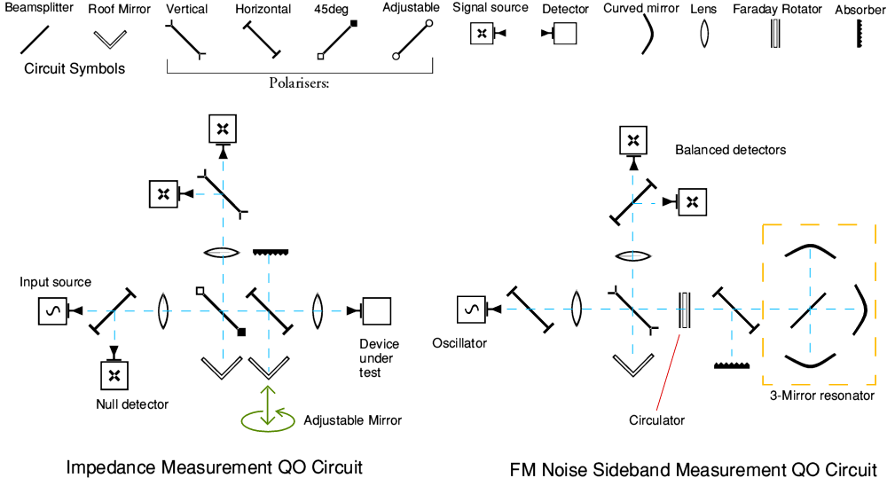
Examples of QO circuit symbols and circuits |
So the overall idea I had at the time was exploring how to design or assess QO ‘circuits’, and then use the book I wrote for the IoP to explain this area of engineering design to other researchers. The diagram above illustrates the process. Across the top of the illustration are the symbols representing the various types of component used. These tend to be ‘optical’ items like types of mirror, etc. Below the top line the illustration shows two examples of QO circuit diagrams. The one on the left shows a complex impedance measurement system. The one on the right shows the system Graham devised for accurate measurements on the noise sidebands of coherent oscillators.
Each of these circuits also appeared in papers they wrote, and in their PhD theses. But here I am just using them as examples of how such circuits can be devised and used. In effect, circuit diagrams give engineers a ‘language’ to think in, argue in, or record their ideas for making systems. Thus it seemed to me that this was needed to enable people to think more effectively about a whole range of tasks where QO might be useful. On a practical level, this approach of working in terms of a standardised set of components also led us to nick... erm adopt an idea which Derek Martin and Richard Wylde had already started to use. This was the concept of the ‘half cube’.

Half-cube on an optical table. |
The above image shows an example. The photo shows a half-cube with a polariser mounted onto its 45 degree angled surface and two lenses mounted on its square faces. Essentially, the half cube is produced by boring two large-diameter holes clear though the block, crossing in the middle. The block is then cut into two ‘cheese wedge’ halves and details then added to allow optical components to be attached. That allowed them to serve as a way to hold components in the required positions for a circuit.
The half cubes were arranged on a flat metal optical table that had a regular array of locating pin holes. Pins fitted to the underside of the half cubes could then be used to assemble them (and any mounted lenses, etc) into an accurately aligned optical arrangement – i.e. a QO circuit. The image also shows, on the right, a simple schematic diagram representing such a half cube seen as if looking down on the optical table from above. This illustrates the locations of a polariser shown in red, and a lens in a cream colour. The areas of lighter grey indicate where the inside of the block has been bored to clear the way for the optical beams to pass through.
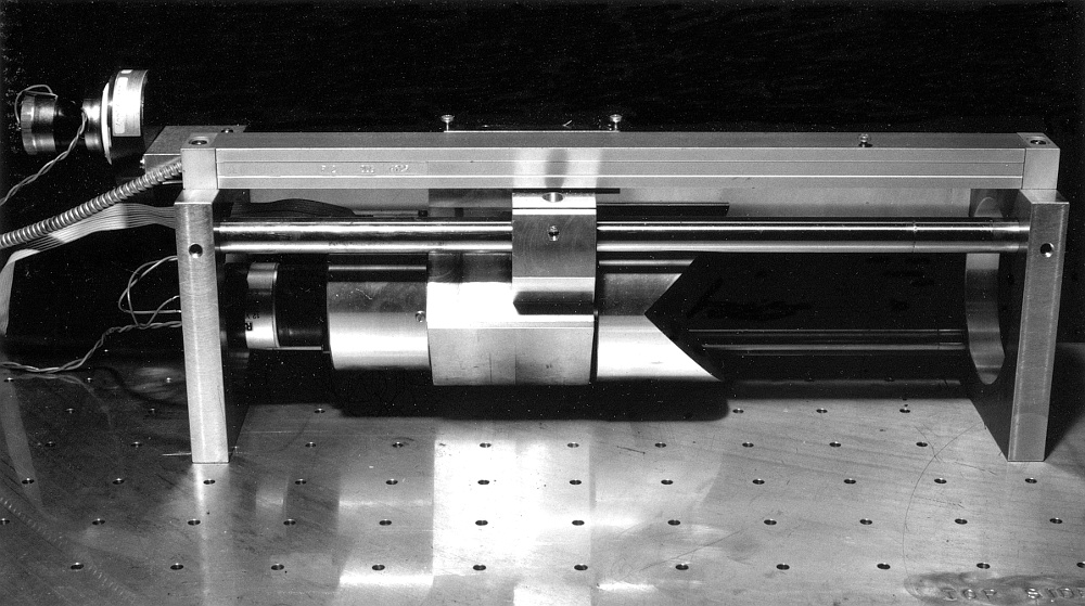
Roof mirror that can be rotated and translated as part of impedance measurement system. |
Sometimes a special-purpose component was required, and when this was needed it was made specifically for the required task. The above shows an example of this, taken from Andy’s Impedance Measurement system. It provides a roof mirror which can be rotated about the beam axis as well as translated forwards and backwards. Combined with a polariser, this provided the ability to generate a reflection whose phase and amplitude could be varied in a controlled manner. The measurement process then operated on the basis of finding the position and angle of this mirror which caused the signal level at a null detector to fall to zero. This null would occur when the mirror setting and the device being tested had the same amplitude reflectivities, but were opposed in phase. That in turn could be used to calculate the complex impedance of the device being tested.
An advantage of such ‘null’ measurement methods is that the precise power level of the input source doesn’t matter. By being based on a simple mechanical (roof) mirror whose reflection properties were well known from basic physics, the results could then be obtained with a high degree of confidence and accuracy. So it was an approach that was well-suited to a primary standards laboratory like the NPL.
As with conventional electronics it was often possible to devise various arrangements that would perform the same task, regardless of having circuit diagrams which differed. This was the case for both Andy and Graham’s work, but eventually each of them settled on a particular design which seemed most satisfactory in use. One nice feature of the half cube approach is that changing around the circuit arrangement was generally quick and easy. This facilitated experimentation – but could also lead to someone, erm, ‘borrowing’ components from your circuit when you weren’t looking! So could be a mixed blessing...
Chris and I spent the Christmas week of 1988 with her parents at their home in Wilmslow. We got home in time for Hogmanay and the next week I resumed work. During January 1989 I sent letters to two of the people who had responded to the adverts for our new research studentship. One of these was Mike Leeson who already had a job in industry but wanted to gain ‘more interesting’ experience. His background made it clear he would fit in very well with the kinds of research and development were doing. As a result he had more to offer than the average student who had just completed their first academic degree.
Mike Webb had contacted me from Australia. He was working for their DSTO (Defence Science and Technology Organisation). As a result he was also already experienced and well motivated. We only had one CASE studentship, but Mike Webb was able to come with support as a DSTO ‘Cadet Scientist’ to fund his PhD studentship at St Andrews. It was clear from the start that both of them would excellent additions to the mm-wave group. Since the CASE studentship was already available, and Mike Webb came with his own funding we arranged that they could both start during the second half of 1989.
Graham started working as a joint SERC/MEDL Post-Doctoral Research Assistant (PDRA) from the beginning of April. His PhD studentship had ended a few months before this, but we had been able to provide some funds from various short-term work to help ‘bridge the gap’. For example, we made and sold some mm-wave oscillators for the BAe company. His initial PDRA award was just for one year, but we were confident that further funding would follow, as indeed, it did in later years. In effect, the award was ‘pump priming’ for later work.
A few weeks later we ordered some InSb (Indium Antimonide) mixers from Ken Wood at QMC Instruments. These were being obtained to provide us with sensitive mixers/detectors, mainly as a ‘balanced pair’ for use in Graham’s work on measuring the noise performance of mm-wave oscillators. Conventional Shottky detectors would suffice for some measurements. However the liquid Helium cooled InSb mixers could provide measurements on oscillators whose power was too low, and/or oscillation frequency too high, for the Shottky devices. They also had a much lower level of internal noise at low output frequencies, so could make better measurements in a number of ways. The snag being the need for liquid Helium cooling. Fortunately, the St Andrews Physics Dept had its own Helium liquifiers and I was familiar with using the InSb systems, so we were able to deal with the practical complications.
Nigel Couch had been one of our main contacts with GEC Hirst and the development there of Gunn diodes. But early in 1989 he left them to take up a job in the USA. Our work with GEC, MEDL, etc, continued, but I was sorry to see him leave because he had done such good work and was so helpful. So far as I recall, my last contact with Nigel was a postcard he sent to me in June. On the 9th of June I sent a letter to Bill Dent at ROE along with a proposal for us to assess developing local oscillators covering the 300 - 800 GHz region for JCMT. This was a response to an ‘‘Announcement of Opportunity” ROE/JCMT had issued inviting people to propose how they should acquire suitable receivers. The proposal included our work on Gunn oscillators, the use of novel forms of harmonic multipliers, and quasi-optical systems. I suggested a one-year project to assess how the required items, etc, could best be provided for JCMT.
During 1989 I was busy writing the mm-wave textbook for the Institute of Physics as well as lecturing and running the research group, chasing funds, etc. More than once during 1989 Chris had come into the room where I was typing the text of my book to find I was working in the dark. I was so focussed on what I was writing, long after dinner, that I hadn’t noticed sunset! There is a popular myth that academics have an easy life because they have ‘long holidays’ and may only give a few lectures per week during term times. The reality is that academics who are active in research have to put far more effort into teaching preparation and non-teaching work than people realise. This may pass un-noticed by undergraduates, but I suspect is something which has become steadily worse over later years.
When we had initially moved from London to St Andrews we had tended to visit ‘down south’ half a dozen times or so a year. Often staying for a week or more. However by mid 1989 this had dwindled to only once or twice a year. And my trips for research work were now rarer and brief. A combination of factors had developed into a set of vicious feedback circles, making things worse. My levels of stress and anxiety had increased due to the combination of worrying about Chris, trying to get work done, etc. Chris’s condition also gradually deteriorated during the late 1980s and into the 1990s. She became more prone to episodes of increasingly severe depression, anger, or confusion.
To a large extent this was driven by her situation of not being able to get a job because prospective employers were put off by her epilepsy. But she also became upset by the sheer amount of time I had to spend working. I was then torn between that and the work I needed to get done. That then made me more anxious about travelling or doing anything else, and not being able to travel so much also upset Chris! My own anxiety wasn’t so bad if we were to travel together, but I was beginning to find it almost impossible to travel without her unless it was for a very short time, and when she was feeling OK. Unfortunately, her episodes of being ‘down’ had become longer as well as deeper. The result was that for both of us, the situation grew worse as the years passed. And we both often felt guilty for how we behaved when looking back after events.
Much later on we started to realise there may also have been other underlying causes that were taking their toll. For example: during this period Chris willingly agreed to act as a ‘guinea pig’ for various medication trials under the supervision of her epilepsy specialist – Dr Duncan Davidson of the Dundee Royal Infirmary (DRI). Some of the medications she tried had unsatisfactory side effects that rapidly became clear. However others may have had side effects which weren’t obvious at the time, but made things worse later on. It is, now, almost impossible to unravel some of the risks Chris took because of her willingness to participate in the hope that the results might help others even if the medication didn’t help her.
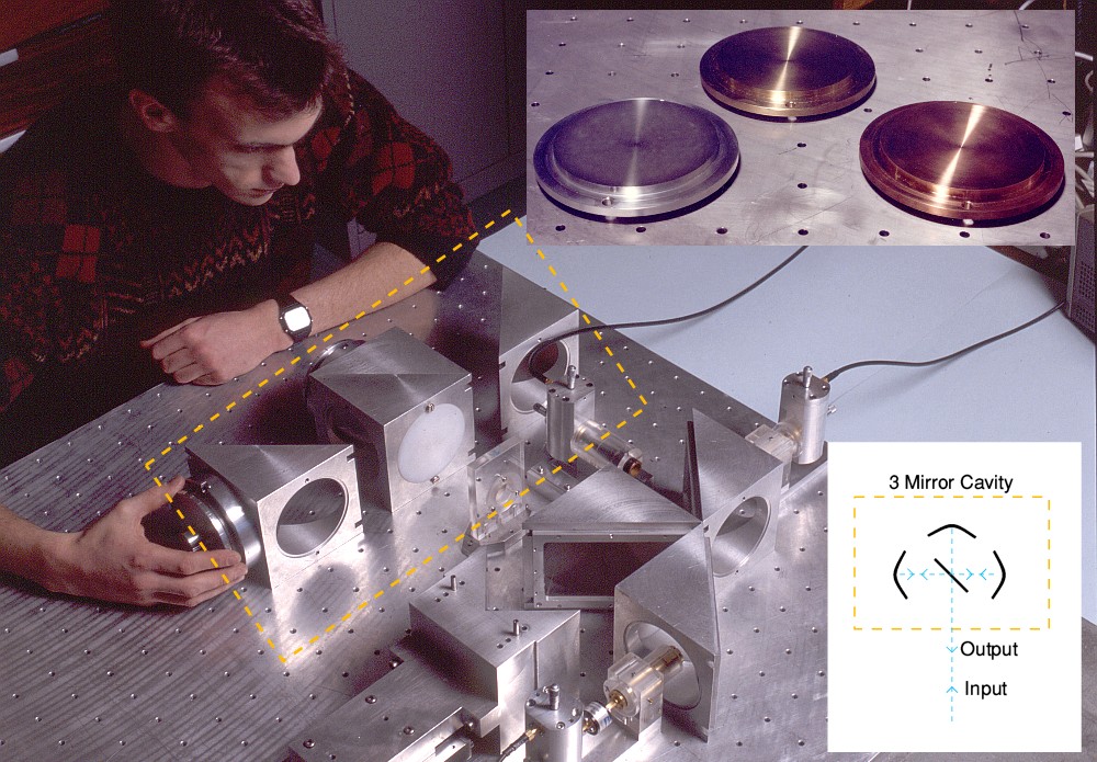
Graham and the noise measurement system. |
During June Graham started to get some initial results from experiments with quasi-optical ‘3 mirror cavity’ resonators. He had worked on these with the aim of using them to allow us to make better measurements on the sideband noise performance of oscillators. The main photo in the above illustration shows Graham adjusting one of the side-mirrors of the 3-mirror resonator in the system he developed. The rear mirror of the cavity is near his wrist-watch. The small image inserted top-left shows three examples of the mirrors which were tested. Different metals were tried to see which choice provided the highest reflectivity.
The insert on the bottom-left shows the resonator arrangement. The aim was to choose a semi-reflecting sheet (beamsplitter) for the center of the cavity which had a very low reflectivity and low loss. Then use this with three metal mirrors whose reflectivity was as close to 100% as possible. The mirrors were all slightly concave to correct for diffraction, etc, and maximise performance.
The semi-reflecting sheet was stretched across the angled surface of a pair of half-cubes. It acted like a flat surface which reflected a small fraction of the incident power. However most of the input beam’s power would usually pass though the sheet because it was almost completely transparent. As a result, for most choices of input frequency almost all the input beam’s power would travel on to the mirror at the back of the cavity and be reflected by that. It then (mostly) would pass again though the semi-reflecting sheet and re-emerge, travelling back along the input path. Hence the overall result is usually that the arrangement behaves pretty much like simply bouncing the input beam off the mirror at the back of the cavity.
However some input power would be diverted and reflect back and forth between the two side mirrors, loosing some power gradually due to each mirror reflection or pass though the beamsplitter. This process of bouncing about would take a given time to go though a ‘round trip’. For some specific frequencies the ‘round trip’ time would equal the time taken for the input signal frequency to go though an integer number of cycles. At such a frequency the repeated internal reflections and the input beam’s initial reflections would all be in phase and add up coherently to a maximum. This generates a resonance condition, and the amount of energy in the cavity rises.
When this occurs there is more power in this internal resonance reaching the beamsplitter, so more for it to reflect out of the cavity. Hence the overall reflectivity it exhibits changes. By adjusting the position of the mirror beyond the cavity we can then control how its reflection and that of the cavity recombine. Arranged appropriately, at such a resonant frequency the result is that the overall reflectivity of the 3-mirror arrangement and its beamsplitter will drop to almost nothing. The result is an arrangement which generally reflects back input signals, but exhibits deep ‘dips’ in reflectivity in some very narrow frequency ranges. In effect, the 3 mirror cavity absorbs the input power at these frequencies.
This behaviour is a direct equivalent of many other types of resonator, and the basic physics involved is much the same. So it is akin to building a resonant circuit using capacitors and inductors, or adding shaped items to a waveguide. In this QO system it was found to provide exceptionally well defined behaviour and a high level of performance. In principle it is similar to the use of tuned circuits in an ordinary domestic radio, and in functional terms, can perform the same sorts of tasks. Its advantage here was that it provided the basis for an exceptionally sensitive way to measure the frequency stability of mm-wave sources, and/or to ‘frequency lock’ them when precise control was needed.
By June 1989 my teaching duties had expanded to giving undergraduate courses on ‘Instrumentation and Signal Processing’, ‘Information Theory’, ‘Radio Communications’, and “MM-Wave Techniques’. I also contributed a series of lectures as a part of the MSc course the Physics Dept offered on what came to be called ‘Photonics’. This was mostly about lasers, but I used to point out that a Watt at mm-wave frequencies gave you far more photons for your money than a Watt at visible frequencies! The 3-year NPL contract which was supporting Andy Harvey was also paying for George Radley to be our full-time group technician, taking him out of the workshop.
We had been awarded an SERC grant, running for three years, in conjunction with Martin Chamberlain and Paul Steenson at Nottingham University. The arrangement was that they would develop and produce novel Multiple Barrier Diodes aimed at being able to function at mm-wave frequencies. Malcolm Robertson would then carry out measurements on their behaviour. During the year up to June we’d sold half a dozen Gunn oscillators – two going to BAe – and this had funded Graham during the gap between his research studentship and his being supported by the MEDL/SERC award. In addition, by this time it became clear that three new research students would be joining the group! In addition to Mike Leeson and Mike Webb, another student, Darrel Smith, was joining, supported by a standard ‘quota’ SERC student grant. So the group continued to expand and bring in more income.
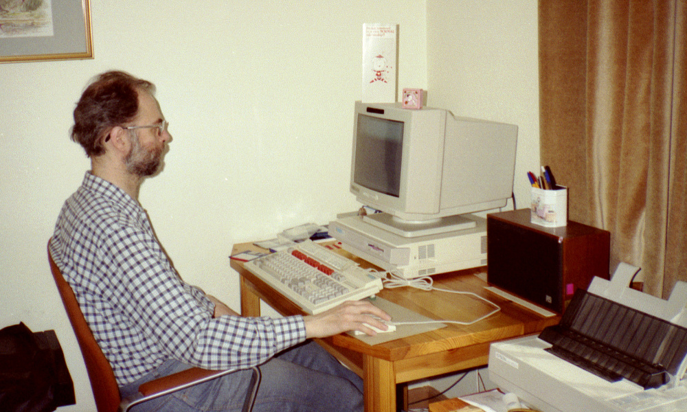
The photo above shows me using an Acorn ‘Archimedes’ computer at home. |
I now wrote all my lecture notes, reports, proposals etc at home. It let me work in a less distracting environment, and meant I could be with Chris more of the time when she was unwell. Having initially bought an Acorn BBC ‘B’ computer I followed on and upgraded to their later machines as they appeared. So went though using a BBC ‘Master’, then the ‘Archimedes’ machines. I also used the same types of computer in my office at the University and to collect data and control instruments in the MM-Wave Lab. One nice feature for practical work was that they could all employ versions of the same hardware interfaces. Hence control and data taking programs that had been used on a BBC ‘B’ could still be used on an ‘Arc’. It seems that I was one of the first University academics in Scotland to buy one of the Archimedes machines. As a result a stream of other St Andrews lecturers, etc, came to my office to see what they were like. In general they were very impressed by them.
Although I wasn’t able to regularly attend meetings of the JCMT User Committee I continued to try to remain involved with the project. However I’d become increasingly unhappy with some aspects of the way things were being done – or more specifically, not done. It was apparent to me that a split was growing between the people at the Royal Observatory Edinburgh (ROE) and Cambridge. I felt this was bad for the project and for the people involved. It also hampered some of the changes I had been proposing.
When mm-wave heterodyne receivers had first been commissioned for the United Kingdom Infra-Red Telescope (UKIRT) it made good sense for them to be developed by a ‘consortium’ of people from different places – QMC, Cambridge, etc. The people working in each location had already developed abilities in specific parts of the required work, Bringing them together allowed complete ‘common user’ instruments to be developed relatively quickly and efficiently. But by the end of 1989 these early receivers were working fairly well, and this seemed to me to provide the basis for future improvements to be done in a more cost-effective and competitive manner. In particular, I felt that we could now define a basic set of ‘interface’ standards and allow more flexibility in deciding who made what items.
The single consortium approach was fine if you were a member of that ‘in group’ of people. In particular, it was useful for ensuring that postdoctoral workers on the related short-term contracts involved remained employed. However each complete new system tended to take 3 years or more to produce, and cost hundreds of thousands of pounds. And anyone else interested in working in the area might find it difficult to compete because these large projects essentially monopolised the funding, etc.
I felt it would now be better to base procuring improved receivers on treating them as a set of modular parts with agreed interface arrangements. Then commission new mixers, or local oscillator systems, or control systems as individual smaller projects with a lower cost and shorter timescale. This would allow more incremental development and avoid re-building satisfactory parts. By reducing the costs it would even allow scope for commissioning more than one researcher or group to develop competing items in parallel and then see which delivered the best performance. More open to newcomers and might help raise the quality of the resulting equipment. Sadly, it became clear that others involved preferred the status quo. Given the desire to try and ensure you can continue to secure funding for good researchers in your own group I can understand this. But I was worried that it wasn’t so good for the end-users and the research councils, etc, who picked up the tab!
For myself, I was prepared to accept that my view was a minority one, and go on trying to do what I could to help with the JCMT project. But I was also becoming unhappy about some of the ‘politics’ that seemed to be being played out between Cambridge University and the ROE in particular. This had two facets. One was the wish to have complete receiver systems that were both ‘state of the art’ and have ‘off-the-shelf’ levels of reliability as common user instruments. Laudable as an aim, but difficult in practice...
The other was a situation where the ROE was required to maintain the receivers and ensure they performed well, but were largely excluded from playing a significant part in their development. As I put it in a letter to someone involved in October 1989: “To motivate people with the required level of (technical) skill you must give them the ability to engage in their own technical R&D”. The ROE people wanted to participate in the receiver R&D, but were prevented from doing so. As things stood, the receivers could be made to work well, or be fixed, when the developers were there using them. But might be problematic when they were absent. Alas, at least one person at Cambridge was determined to ensure that they could go on feeling they were the prime center of the relevant R&D in the UK. So a situation developed where the ROE and Cambridge had to work together on a basis which the ROE people objected to. I felt this wasn’t either fair or best for receiver development. I did write to people expressing my views, but then had to leave any decisions to them. In practice, the bulk of the work we were doing at St Andrews wasn’t directed at mm-wave astronomy anyway, so I left the issue for others to argue out to a conclusion.
In November Andy had almost finished writing up his PhD Thesis. So I wrote to Derek Martin at QMC, inviting him to be Andy’s external examiner, and to start the process of arranging a date for the viva – which at that point I estimated might be in February or March 1990. But in reality it didn’t happen until much later because Andy kept being too busy with other paid work! Graham was going though a similar process of never quite getting around to finishing his PhD thesis because he was concentrating on work paid for by his research post. Thus the following months became a sort of “who goes last” competition to see which one of them could postpone actually getting their PhD until after the other! I started wondering if I should ask for a “long service medal’ for being their supervisor. However I couldn’t really complain too much because I’d taken nine years from starting my own research studentship to get my PhD. So pots and kettles came to mind whenever I tried to push them to get on and finish their thesis.
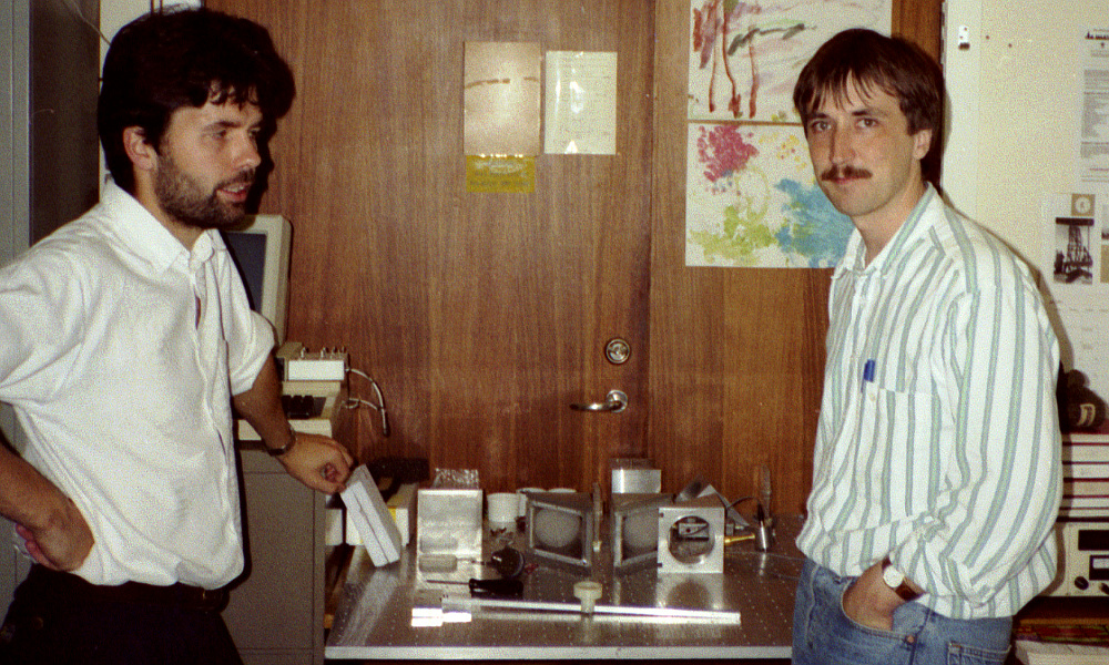
The above photo shows Mike Leeson (left) and Mike Webb (right) in the MM-Wave Group laboratory. |
By November the mm-wave group had grown to include four research students. In addition another member of the St Andrews academic staff, Roger Edwin, had begun working with us. Roger was nominally an astronomer, but had worked in the past at the NPL and specialised in instrumentation. So although he had no previous experience with mm-wave optics, he was a useful addition and expanded what we were able to do.
I had by now almost completed writing the book on mm-wave optics. So in December I wrote to the IoP to suggest that once it was finished I should go on to write another textbook for them, this time on ‘Information and Measurement’ (I&M). The mm-wave book was aimed at the research level, and one of my reasons for writing it was to save my having to explain the same things to every new research student. However the I&M book was to be for undergraduate teaching purposes. I had been giving a set of undergraduate courses that covered Information Theory (IT), communications, and measurement. As a result I had been reading though a number of the common undergraduate textbooks for these areas. I wasn’t keen on their approach to IT in particular. They tended to be mathematical, very abstract, and theoretical.
Frankly, I’d also found that many of them used ‘explanations’ in places that were either opaque and/or simply wrong! Indeed, in some cases the brain-baffling opacity or complexity of the ‘explanations’ actually camouflaged the reality that the arguments used were incorrect. More than once I suspected that the authors hadn’t understood this and had simply transcribed them from earlier texts, taking for granted they were OK! Hence although some students were happy just to become familiar with the maths in these books and pass their exams, taking for granted that meant they ‘understood’ the topic, they seemed unsatisfactory to me.
As an engineer/physicist I also felt it would be useful to have an I&M book that based its explanations on an understanding of the relevant physics, and on the way information about the real world starts with a measurement of some kind. My lecture notes had tended to adopt this approach, so were the seed of what I aimed to write. The editors at IoP agreed with my proposal. We therefore arranged that once work on the mm-wave book was complete I would begin writing one on I&M, aimed at undergraduate scientists and engineers rather than mathematicians.
N.B. For anyone interested - a free PDF copy of this textbook can now be obtained from: http://jcgl.orpheusweb.co.uk/InformationAndMeasurement_PDF_Book_pf.pdf
In December the SERC turned down a joint research proposal for work in collaboration with MEDL, Lincoln. However this was because – as an embarrassed Sean Neylon of MEDL admitted to me the next day – he’d forgotten to submit some of the forms MEDL were required to send to the SERC! As a result, MEDL agreed to fund some of the work anyway. Thus providing more money for Graham’s research. His ‘Noise Bridge’ system was providing resonator ‘Q’ factors of up to 400,000 and as a result were already exceptionally sensitive as sideband measurement systems. But we continued to improve this and build on what had been achieved.
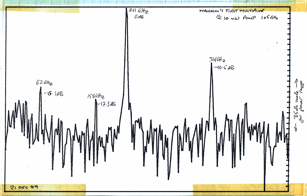
One of the first results produced by one of the MB diode multipliers. |
The above shows one of the first spectra from the MB diode multipliers Malcolm built and tested. Note the frequencies written onto the graphs are approximate because the resolution of the spectrum was low. So they are only accurate to a few GHz.
By the end of 1989 Malcolm’s work on using diodes as frequency multipliers was starting to provide some interesting results. I sent copies of the spectra produced when these diodes were driven by our Gunn oscillators to Jim Birch at the NPL because they were one of the organisations wishing to obtain solid state sources for the higher frequencies the multipliers had the potential to provide. The graph above was one of the examples. One feature of the behaviour of these early diodes was to become significant later on. The largest component – listed as being at about 211 GHz – is actually at double the input pump frequency. But the second largest is at about 361 GHz, which is around 3·5 times the pump frequency!
People who stayed in Scotland during the late 1980s and into the 1990s will recall the ‘Poll Tax’. This was imposed on Scotland by the UK Government – essentially using Scotland as a guinea pig for imposing it on the rest of the UK later on. It was a mediaeval idea, idiotically introduced for ideological reasons by the Government in Westminster, and was hated by the Scots. The idea behind it was simple minded – that everyone should pay exactly the same amount of tax, regardless of their circumstances or ability to pay. The snag was that many people simply were too poor to be able to pay. There were mass protests and various kinds of actions to oppose the tax. Chris and I could afford to pay, and indeed, it would cost us less than the alternative taxation schemes which were based on income, house valuation, etc. But like others, we felt it was an unjust imposition that should be resisted.
The approach I took was to dispute the various communications from those trying to run the tax. These came to me as what they referred to as the ‘responsible person’ for our household. Initially asking me to officially confirm I accepted this status and who lived in our house. I objected and wrote back asking why I was given this status and not Chris. Was this because she was regarded as ‘disabled’, or female, or a wife, and thus inferior? If so, this was clearly discriminatory. Were we required by law to accept whoever had been designated as such?
There followed an exchange of letters over some months as we devised various ways to challenge the way the tax was being imposed. And each time I got a form I sent it back, unsigned, accompanied by such a letter. We were, in practice, paying from the start regardless of our objections. The local council already knew my bank account details from having taken their previous ‘rates’ based on the assessed value of our home, and proceeded to take the new payments whatever objections I made. In itself that was OK with me as I didn’t want the council to be denied the income they needed. But I, and others, could at least register our objection to the basis of the tax and join in the protests, etc. It took a few years, but in the end the poll tax was abolished and the Government which had inflicted it also consigned to the dustbin of history.
For research students who joined the group directly after finishing a first degree I tended to arrange that they would spend their first six to twelve months working on various small tasks. This was to give them time to become familiar with different aspects of our work, and how research was done. In the process, they could discover what particularly interested them, and what talents they had before we chose a specific topic for their PhD. However Mike Leeson and Mike Webb came into the group with useful experience and skills. In Mike Leeson’s case, his work was also funded by EEV to work in a particular area. So after just a few months we were mapping out what was required for his main project. This was to develop a ‘demonstrator’ system for a 140GHz dual-polarisation Continuous Wave Frequency Modulation (CWFM) radar system using quasi-optical circuitry. As a result, by February 1990 the initial design work was done and I was arranging with EEV for the required items to be built so the system could be assembled and testing begun. I had planned to visit EEV Lincoln on the 12th, but this had to be postponed because I was unable to go. During February I also wrote out a detailed synopsis of the planned book on Information and Measurement having go the initial go-ahead from IoP.
The group continued to make Gunn oscillators for sale to various external users. This was often a ‘bespoke’ exercise and we tried to tailor oscillators to meet specific user requirements. However it meant the cost – and thus price – varied accordingly over a range from £3,000 to over £5,000 per Gunn oscillator. One particular problem was that the diodes capable of the highest output power and/or oscillation frequencies tended to be much more expensive to obtain from commercial suppliers than ‘run of the mill’ lower power examples operating in the 75-95 GHz region.
Another complication was that these devices were classified as ‘munitions’ by the USA! This was because they were used in some USA/NATO defence equipment and they were determined to prevent them getting into the hands of the old USSR. Hence we had to get official clearance and approval when buying the diodes from the USA. By this time GEC/MEDL were starting to also make good Gallium Arsenide (GaAs) Gunn diodes and we could obtain these via our research link with them. Alas, as research items they weren’t always a reliable source for general users. The highest power/frequency Gunn diodes were made using Indium Phosphide (InP), and at that time were only available from the USA on a commercial basis. Another complication was that the main suppliers of both types of Gunn diode – Varian of the USA – set a ‘minimum order’ level. So you couldn’t buy just one diode at a time, you had to buy at least about a thousand pounds worth at any one time.
As a result we sometimes had to spend time discussing with a potential user of an oscillator how best to proceed. One example of this was during February 1990 when we arranged for someone to pay for two diodes, and we would then use the ‘best’ one for them in the oscillator we supplied, but keep the other diode for our own use. In return, we arranged for a discount on the price of the oscillator we supplied. This worked out fine all around, but complicated the entire process. Having developed the ability to make good Gunn oscillators, one nice result was that each one we supplied was an opportunity for one of the group’s research students to make a few hundred pounds by being paid to tweak and characterise the oscillator and get it operating as specified before it was sent to the customer. Given the low level of postgraduate grants this was welcome bonus for the research student who did the work. The process also fitted in with another aspect of my approach to research and teaching research students.
Having spent some time working in manufacturing industry before returning to academic life I was well aware of some of the key differences between them. Given this, I felt it was good for research students to gain some experience of what might be expected from them when employed beyond a University. In particular in an environment where work that was paid for needed a different frame of mind. In academic research it was common for a grant to be awarded on the basis of a proposed outcome – only to find at the end that the results were rather different. This tended to lead to final reports which said, in fancier language, “You paid us to investigate A, but we found that B was much more interesting – so we did that, and here’s what we found out.” This could be fine for pure research – particularly if ‘B’ was a remarkable discovery and useful in its own terms. However a commercial business that had to make things, under contract, for a specified purpose would require the work to be done to spec, on budget, and on time. In effect, to get what they needed in exchange for their money. Not something else that might be interesting, but they couldn’t use.
Hence when possible I tried to arrange that research students became accustomed to this approach. In itself, it was a saleable skill for them when seeking a job in industry. Being able to point out that they had successfully delivered projects on this basis would be useful for their c.v. It can also be pleasing to know you are able to make useful items, and have skills which others appreciate.
During February and March 1990 I wrote another article for New Scientist magazine. This time the subject was “The Rise and Fall of Negative Resistance”. The results appeared in the issue cover-dated 31st March 1990. It provided a general introduction to negative resistance (more properly called ‘negative differential conductance’) and used some examples taken from Malcolm Robertson’s research on Multiple-Barrier (MB) diodes and the Gunn diodes.
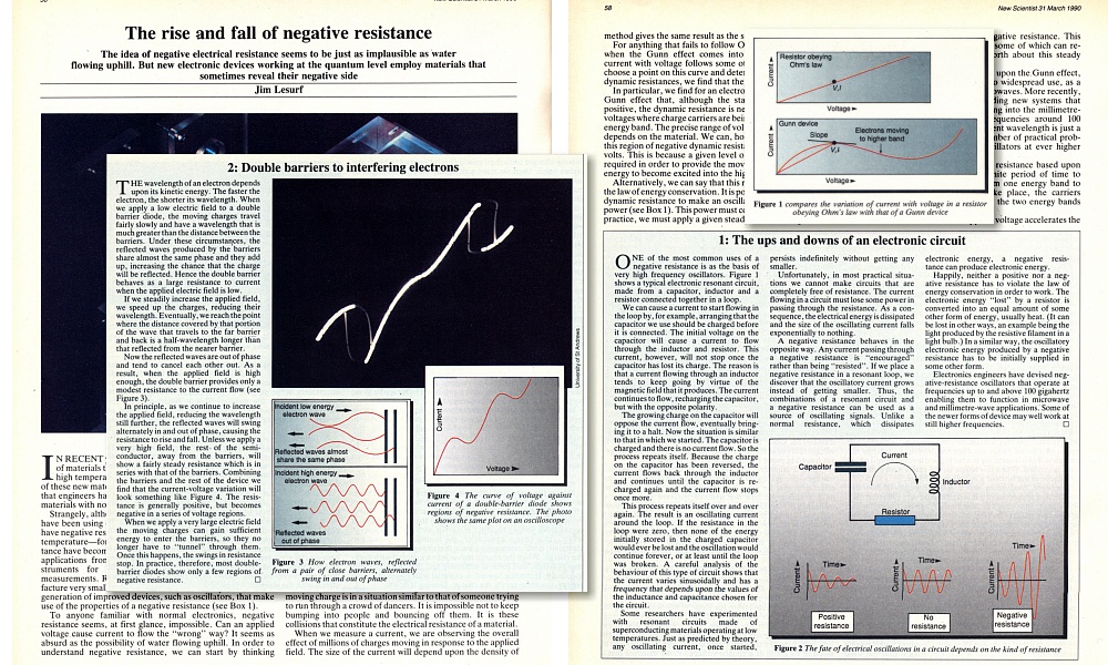
The rise and fall of negative resistance. |
The MB diodes worked on the basis that in the right circumstances electrons will behave like waves. So by placing a series of different semiconductor layers close together in their path it was possible to make the combination act in a way analogous to an optical Fabry-Perot Resonator made from parallel sheets of semi-reflecting material. Some wavelengths (i.e. electron kinetic energies) would be reflected more than others. The result is a resistance to conduction that varies with the applied voltage. These variations allowed the devices to act as nonlinear mixers or multipliers. And if some sections of the resistance variation had a negative slope, also as oscillators. The New Scientist article included a photo of the IV-curve of one of the diodes being plotted on the screen of an oscilloscope. This showed characteristic ‘loops’ where the curves had such negative slopes. The MB diodes were produced by Martin Chamberlain and Paul Steenson of Nottingham University.
Our initial interest in MB – also Quantum Well (QW) diodes – was the possibility of them being able to extend our ability to make solid state oscillators up to higher frequencies. The GaAs and InP Gunn devices would reach up to around 150GHz but the properties of their materials made it difficult to for them to oscillate at higher frequencies. The MB/QW devices used a quantum mechanical effect and as a result had the potential to operate at much higher frequencies. Hence Malcolm’s main focus at the time was exploring these possibilities, trying out devices to see what they might be able to do.
Jim Lesurf
31st Oct 2018
7500 Words