Typical Homes in Scotland?... |
A Very Busy Time...
|
Typical Homes in Scotland?... |
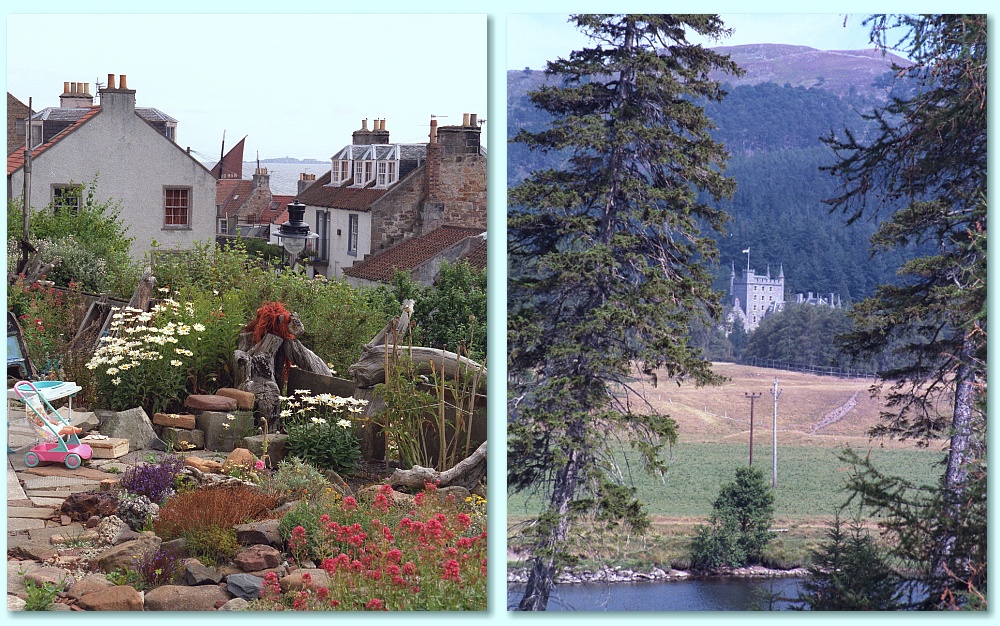
John Scott came to visit us in the summer of 1995 and we took some trips together around Scotland. The above photos were taken by John. The one on the left is a view in Pittenweem on the south coast of the Kingdom of Fife. The other shows Balmoral. What struck me about Balmoral is that – seen from afar – it reminded me of a Glasgow tenement, but perhaps with an unusually large garden and battlements!
Looking back at that time from the present (2019) it’s clear that the second half of the 1990’s was the busiest and most successful period of my life as a research scientist. In essence, my work peaked during those years. Sadly, it also meant I was under a lot of stress, and this had its consequences later on. My wife, Chris also became increasingly unwell during this period. However, at the time I found the work exciting and very satisfying, and the St Andrews MM-Wave Group was very active.
As was traditional, I started 1995 with a bought of flu leading to a secondary infection over about six weeks including the Christmas holiday. This caused nasty symptoms like coughing up blood on occasion and feeling awful. So the ‘holiday’ wasn’t the rest we’d hoped for! Before Christmas I’d had to re-write many of my lecture notes because the way courses were arranged had been altered. The new arrangements were more logical, but getting there was a challenge.
At home the most obvious issue during the first half of 1995 was apparent whenever we went out into the garden. When we’d moved to St Andrews one of the first changes we’d made was to replace all the old windows with new double glazed units. When doing this we decided that the window in the living room at the back of the house should be replaced with french windows that opened out onto the garden. These immediately gave a better view of the garden. However until 1995 we hadn’t made any alterations immediately outside the french windows.
This meant that there was a large step down from the windows to the ground outside. We’d also left the flowerbed unchanged. So to go out via the french windows meant either a large step down into the soil of the flowerbed, or a leap over it onto the grass! We’d put up with this for years but Chris decided we really needed some steps and a patio. She also wanted the patio to be shaped with a pattern of curved outer edges rather than being a plain rectangular block of crazy paving.
We had a couple of builders around to explain what we wanted and quote for the work, then chosen one. I’d made one quite specific requirement which we made plain was essential. The patio’s surface must slope slightly away from the house. This was to prevent rainwater from ‘pooling’ up against the side of the house. Partly because we didn’t want to have to step down into, or jump over puddles. Partly because we worried that a pool against the house wall would lead to other problems. However despite the builder agreeing, and a plan drawing made by Chris, being accepted by the builders, things didn’t go to promised.
Once the concrete base was laid it was clear that the shape of the patio wasn’t what Chris had specified. Instead it was a shape that was much easier to trace out on the ground with two sticks and a bit of string. On inspection, it was also obvious that the base wasn’t sloped as specified. But when we asked the builder who was doing the work he insisted these details would be fixed when the paving as fitted on top of the base. Alas, this turned out to be untrue...
I checked and the crazy paving surface of the patio had a curve. The parts well away from the house did slope away, but the parts nearer the house sloped towards the house. Having pointed this out to the builder his main reaction was to not appear for another month, leaving us with an unfinished patio that wasn’t to the agreed specifications, plus large piles of sand, etc, using our garden as a temporary storage area. Phone calls were ignored, etc. Another builder we had look at the work agreed it would need re-doing and commented that even the materials used for the base weren’t the sort required!
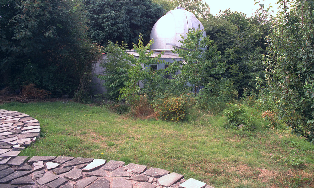
View of our back garden in 1995. Note the (very!) crazy paving in addition to the dome. |
By this time Chris had resorted to having the Citizen’s Advice Bureau send letters to him, asking for the work to be corrected so it was as we’d agreed. The chain of events then extended over many months and into 1996. We found another builder who agreed to re-do the paving as required, but he also took a deposit, never to appear again! After repeated direct attempts to get them to do the work we resorted to having a lawyer send registered letters to the builder requesting the return of the deposit we had paid. However when these arrived he refused to come to the door, so the GPO had to return them as refused. Fortunately, neither of the builders cemented in the gaps between the paving slabs, nor fill in between the ‘patio’ and the house. So by leaving these unfilled we allowed the area to have a set of drainage channels which avoided the ‘pooling’ which had concerned us. We just ended up adding some simple steps of our own. The final result was a quirky ‘patio’ of a kind you’d not see elsewhere, for the price of a deposit and a load of argument. The other outcome was to conclude that many people who advertised as ‘builders’ couldn’t be trusted further than we could throw a stack of paving slabs, and that requests for any form of ‘deposit’ were a sign that we should try someone else! I’ve also come to suspect that builder number 2 was a mate of builder number 1, sent to try and extract some cash from us for his shoddy work.
Duncan Robertson’s Ph.D. viva took place on the 26th of January. As usual, I’d arranged for the viva to be in the morning, and then to go with him and the external examiner for a good lunch to celebrate. There was never any doubt that he’d pass. His main problem had been to actually finish writing his thesis in amongst all the other things he was doing as a part of our research work!
At the start of February I wrote a letter to ‘Physics World’ (the magazine for members of the Institute of Physics) reacting to an article they’d published which was on the use of personal computers in physics. It was one example of a number of similar letters I wrote during the period on this topic. The main point I felt I had to keep making was that, during the late 1990’s, articles, radio/TV reports, etc, frequently dealt with computing using the presumption that only two possible kinds of personal computer existed – IBM/Windows ‘PCs’ or Apple ’Macs’. Whereas the reality in the UK during this period was that many schools, colleges, universities, and also companies, used the ‘Acorn’ computers which ran the RISC OS operating system using quite different processors, etc. These tended to dominate use in some areas like schools. But they were routinely ignored by the media in general.
A couple of weeks later, for example, I wrote a letter to the editor of New Scientist about a particular issue of this kind. The Advertising Standards Authority had already issuing a finding that some adverts produced by Apple were misleading. In effect they were claiming to be the first to release ‘RISC’ (Reduced Instruction Set Computer) processor based computers for use by the general public. This simply wasn’t true because Acorn had already been doing so for many years. Apple had no real excuse for not knowing this as they had previously been involved in a joint venture with Acorn. However despite this ASA ruling, New Scientist had on a couple of occasions had carried the misleading claims so I wanted to alert readers to this point which had been given little publicity.
The ‘TopSpin’ Electron Spin Resonance system that Graham Smith had developed was coming into regular operation during the first months of 1995. At our invitation a number of scientists who wanted to have measurements made using the system had joined a ‘TopSpin Club’ we’d formed. On the 6th of March we sent out copies of a newsletter to them to keep them informed. This reported that the system was now working well in the 90 - 140GHz range, with higher frequencies (and thus magnetic field levels and resolution) planned for later in the year.
The Long Hot Summer of 1995 |
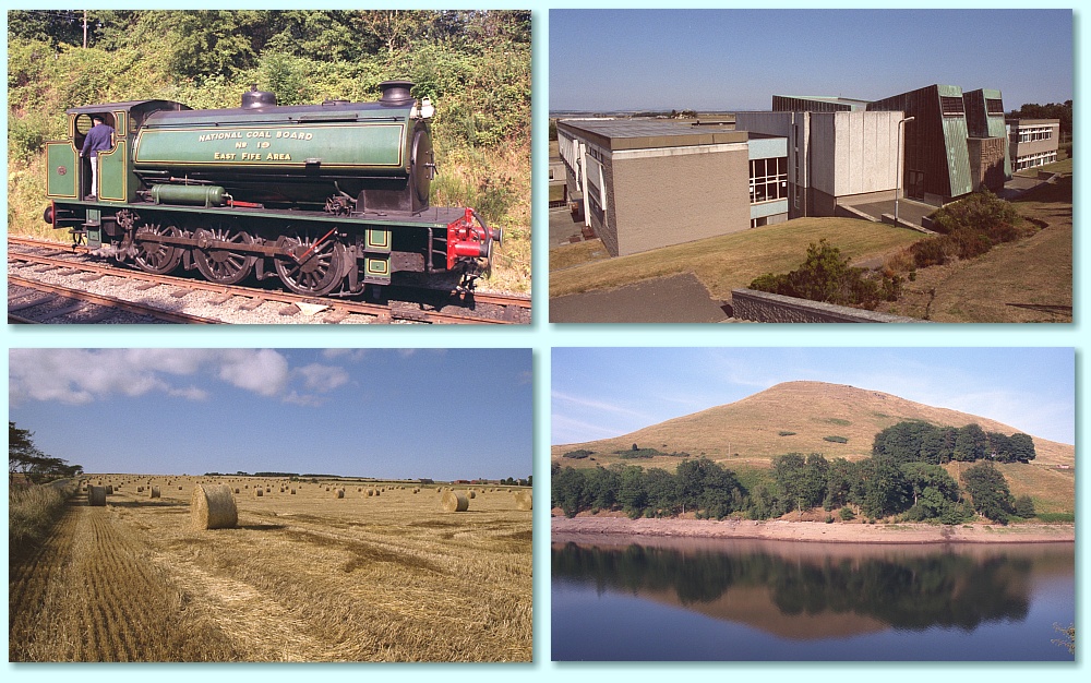
The summer of 1995 was particularly warm, sunny, and dry across Fife. This shows very clearly in the above photos taken by John Scott. The (top left) picture of the steam locomotive comes from when we visited the Bo’ness Preservation Railway. To the right is a view of the physics building from the top of the hill behind it. The lower pair of photos show some giant Weetabix in a field just outside St Andrews, and a view across Glen Devon reservoir. You can see that the water level in the reservoir was unusually low at the time, and that the day was hot and calm.
In addition to the mm-wave work of various kinds I had also recently taken over the use of the Physics Department’s (acoustical) anechoic chamber. A research student, Ian Dennis, was taken on to work on acoustics. In part this was funded by DERA to see if we could apply the same spatial interferometry methods to audio signals as we were developing for use in the mm-wave region of the electromagnetic spectrum. Given my personal interest in audio and Hi-Fi we were also looking at using the chamber and spatial interferometry for audio research. As a result, in March we had some discussions with Charles Brennan who was one of the directors of Tannoy Ltd in Coatbridge at the time. This was to see if we could produce some novel measurement techniques for them, or contribute to developing new ideas for loudspeakers. During March I also found myself doing some analysis on the sound patterns radiated by crickets (the insects) to try and help a researcher in the Biology department answer the question, “How high up the stem of a plant should a cricket climb in undergrowth to maximise the range of its call in dense plantation areas?” So the number of people working in the group, and the range of work I was doing steadily increased during this time – sometimes in quite unexpected ways! Perhaps the oddest was a result of a conversation with one of our neighbours.·
In 1995 our neighbours on one side were Mike and Moira. Mike was a Japanese/English translator, specialising in technical documents for various companies. His skill was knowing both languages very well. But he sometimes didn’t understand the full technical basis of what was written. So I occasionally helped him by looking at the English version he had and spotting any potential misunderstandings or statements that were ambiguous. Given how different the Japanese and English written languages are, it was quite a fascinating exercise.
For some time I had dithered over deciding if I should apply for promotion or not. One drawback was that a recent change had been made to the meaning of ‘tenure’ for UK University academics. In essence, up until the 1990s once an academic had full tenure it was almost impossible to make them redundant for any arbitrary reason of University convenience, etc. The legal status was then changed, making it easier to sack staff, but only for new appointments. The snag being that this included promotions. In reality this hadn’t bothered me because I never did want to be promoted to a professorship even if someone had been crazy enough to offer it to me! So far as I could see, although professorships brought in higher pay, they also tended to mean being saddled with lots of committee work, form-filling, etc, of kinds I was keen to dodge. However I had concluded that promotion was useful when it came to impressing people into giving us research project funding. So I’d decided to apply for a ‘Readership’. This probably isn’t a job title most people outside UK Universities will be familiar with. But in essence it signifies someone whose work in a mix of research and teaching is particularly good, but not sufficiently outstanding to gain a professorship. Sort of half-way-house. But useful on proposals which seek support for research work.
As a result, I’d put in an application with a detailed CV, and this had been rejected at the start of 1995. I wasn’t particularly surprised by this as it was my first go at putting forward such a proposal. However when I looked at the details of proposals which had been successful I was struck by the extent to which – on paper and according to the stated criteria – the successful applications were actually weaker than mine. By this time I had enough confidence in my track record to start making further inquiries and to ask the academic in change of the process about this situation. And I decided to apply again at the end of 1995 for the next round of promotions.
During 1995 Chris became steadily more disappointed and depressed by the way Fife Council were treating the Citizen’s Advice Bureau, and the prospect that it was going to be replaced by a Council owned and run organisation. This meant that she was starting to look for some other kind of voluntary work she could do. At the time a very good friend, Margaret Squires, was about to end her participation on Fife Health Council (FHC) and suggested that Chris apply to become a member of their committee. At the time the FHC acted as an channel / intermediary between the Fife Health Board (FHB) and the general public. The FHB was a professional body legally responsible for managing and overseeing the NHS provision in Fife. The FHC was established to help members of the public scrutinise the work of the FHB and bring forwards concerns, problems, and ideas that might improve the operation of the NHS in Fife. Margaret and the organiser of the St Andrews CAB provided references recommending Chris, and she was given a place on the FHC.
Over the next few years membership of the FHC involved her in many meetings, etc. all over Fife and occasionally elsewhere in Scotland. The meetings were often several hours travel from home, and she often went by bus because we had no car and as someone with epilepsy she wasn’t allowed to drive if we’d had one, anyway. This was in addition to her work at the CAB which continued until in later years it was shut down by Fife Council. So became quite active, out most days at meetings or the CAB.
Chris used to regularly phone her Father who her had stayed in Wilmslow after Chris’s Mother had died. At the start of June 1995 she found his phone ‘wasn’t working’, and contacted one of his neighbours who’d promised to keep an eye on him. He was OK, and the phone began working again some time later. At the time we assumed it was just a fault which had been fixed. However looking back on it later we now suspect it was an early sign of the dementia he developed in later years, and had simply forgotten to pay the phone bill despite reminding letters to so do.
In the middle of June Chris went to Glasgow for the Scottish Association of Health Councils (SAHC) conference. She found this very interesting. But over the months as she gained experience with the FHC she became increasingly unhappy with the way the operated. She came to feel that it was largely ignored by the health board, and even the employed staff who were meant to work for the FHC. In practice, the staff tended to run the FHC as suited them and the board, not the members or general public. This was all done with a friendly and polite manner, but ideas that didn’t ‘fit in’ were simply ignored. Membership gave Chris a chance to find out what problems members of the public encountered, and what might help them. And she enjoyed trying to help. But getting any changes to deal with them was like wading though treacle.
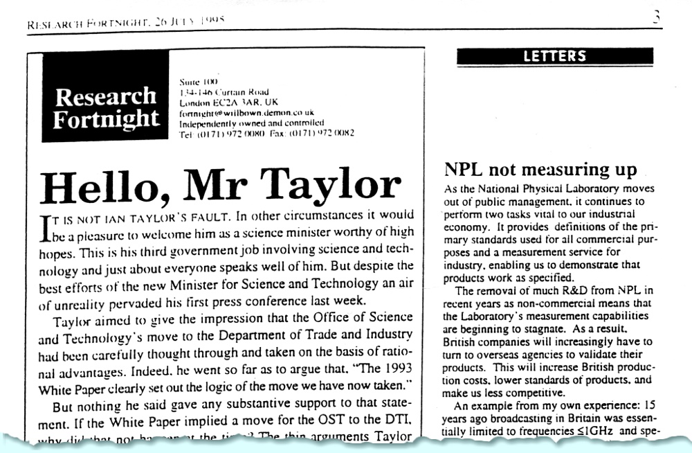
Research Fortnight 25th July 1995 |
On the 25th of July the specialist journal ‘Research Fortnight’ published a letter I’d sent to them about the ‘privatisation’ of the National Physical Laboratory. I chose this publication because I know it was widely circulated and read by politicians and civil servants with an interest in science and industrial policy as well as by researchers in industry and academia. The views I expressed were ‘out of favour’ with the Government of the period, but chimed with the concerns of many in UK industry. I knew from direct experience that this change had lead to a dramatic reduction in the areas of standards work undertaken by the NPL, and that this worried people in all these areas.
The risks weren’t only that important areas of standards setting and checking might not be available when UK industry needed them. There was also the risk that a privately run NPL might regard its methods ‘commercially confidential’ and thus undermine the ability of others to verify how their results were obtained or spot flaws. And if the organisation came to be owned by a company that also made items which needed to be standards checked there would be a clear conflict of interest. In the same way as when I’d publicly raised objections to other changes, various academics, etc, privately agreed with me, but felt it was a ‘brave decision’ (in “Yes Minster” terms) for me to speak up as I did. Fortunately, in the end, few problems arose, but the risks were present. And in some areas of technology the NPL did, alas, lag behind standard bodies in other countries as a results of cutbacks and commercially-driven decisions.
During August, John Scott came and visited us in St Andrews for week. This was wonderful as he was (and is!) a great friend and we thoroughly enjoyed his visit. For me it was a great break from hard work. Since he’d travelled up by car he wanted to use the chance to explore Scotland. So it was also a chance for us to go with him and see places we’d otherwise never have visited. John decided that the thing to do most days he was here was to simply ‘drive north’ taking almost random decisions at times about which route to take. As a result we reached many places, some of which are well known like Balmoral or Glenshee, whilst many others are rarely visited by tourists but looked wonderful. At the time there was a drought in Scotland and some of the land looked quite parched and yellow rather than green. John was, and still, is an infinitely better photographer than me and has the eye of a visual artist/graphic designer. So it also left us with a legacy of a series of excellent photos he took whilst here!
A cover story... |
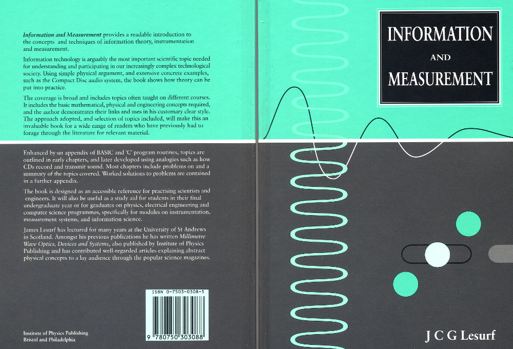
Around the middle of 1995 the Institute of Physics issued the hardback first edition of an undergraduate textbook I’d been writing on “Information and Measurement”. This had evolved out of being asked to take on an undergraduate lecture course on Information Theory when I’d started work at St Andrews a decade earlier. At the time this was a short course given by a theoretical physicist who by coincidence had also worked at QMC before coming to St Andrews. The short course had concentrated on the mathematics of information theory. However I decided to make the course wider to be able to place information theory into the context of physics. Thus showing its basis in physical measurement and reality. To me this was an obvious approach given that measurement systems ‘produce’ information in the form of meaning-carrying ‘data’. But to fully understand what that information mean you need to understand how it was produced by the measurement system which it comes from – be that a music recording studio microphone or a complex instrument on an astronomical telescope, or at the NPL or even a sensor on a tank on a battlefield! It also helped to show how ‘data’ and ‘information’ aren’t the same thing, etc.
An updated second edition of the book was issued as a paperback a few years later. That is also now out of print. But anyone interested can now obtain a free PDF file version from here: http://jcgl.orpheusweb.co.uk/InformationAndMeasurement_PDF_Book_pf.pdf
While putting the initial course notes together and then writing the textbook I also realised this was another area like Electromagnetism where many of the standard undergraduate texts either skated over really explaining some of the basic ideas or – in some cases - gave false ‘explanations’. For example, many books gave an explanation of the basis of Shannon’s Equation (one of the basic equations of information theory) using some brain-baffling descriptions of multidimensional topology. I puzzled over this ‘explanation’ in many textbooks before going back to Shannon’s original papers on the topic. After a while I realised that these common textbook explanations were actually wrong. As in some cases I found in electromagnetism, the complications of the ‘explanation’ made them so baffling that people had simply assumed they were right even though they didn’t understand them. So it got copied from one generation of textbook to another without passing though the mind of the authors! However by thinking about simple real-world signals I found a much clearer way to explain how Shannon’s Equation could be seen to be correct. Possibly because I approached the topic as an simple-minded engineer not a mathematician.
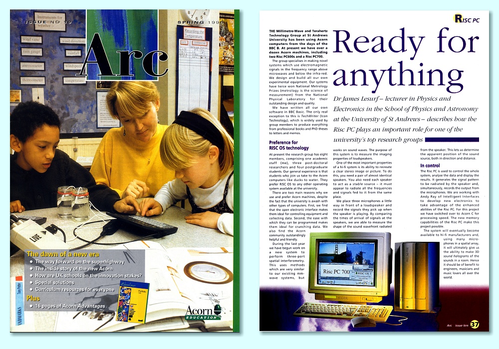
Arc Magazine and article |
During October I wrote an article for ‘Arc’ magazine on RISC OS computers. This appeared at the beginning of 1996 and was sent out to schools, colleges, etc. I gave some examples of the kinds of uses we had for the then-current Acorn RiscPC machines. In November I submitted a fresh Readership application for promotion to the relevant University committee and awaited their deliberations again...
The bulk of my research work during this period was directed at projects for the Defence and Research Agency (DERA). One consequence was that large chunks of my time were paid for by them to work full-time on MoD/NATO projects. Nominally, this meant I was granted two ‘sabbatical’ terms, but alas, I was still expected to give the undergraduate courses which I’d normally have presented then. They were just shifted to other terms! During these years Duncan Robertson was funded via DERA and, along with Peter May, did the bulk of all the hard practical work whilst I tended to do a great deal of analysis, mathematical modelling, instrument design, presentations to committees, etc. The result was a stream of reports which I submitted or presented to DERA on various aspects of the research.
Our activity was based on two general topics.
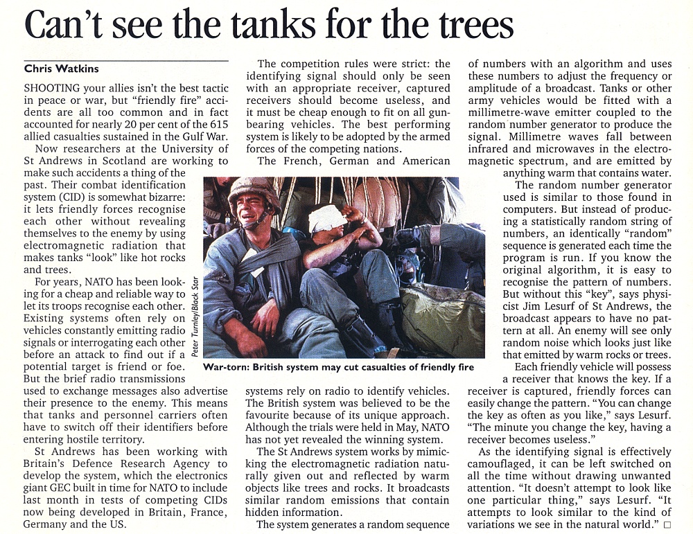
The main area of application that was driving the interest in these topics was CID (or BIFF) which stood for Combat IDentification and Battlefield Identification Friend or Foe. These actually allowed us to bring together the main techniques Duncan and I had become interested in over the previous years.
The LPI work was, for us, based on my earlier interest in chaotic and semi-chaotic oscillators. To show why it was relevant I can start by looking at a technique which is more widely known and understood. The idea of ‘frequency hopping’ a signal.
Hop to it! |
The animation above illustrates the technique. The orange-ish lower part of the power-frequency plot represents the average background noise level. The blue ‘spike’ represents a transmitted signal.
The original context for the invention and use of frequency hopping was it being employed as a way to allow a signal to ‘dodge’ being jammed by an enemy. The technique arranges for the information-carrying signal to ‘hop about’ in its chosen transmission frequency. This means anyone trying to eavesdrop on or jam the signal has to try and keep ‘catching up’ with the – apparently random – hopping about. As such, it is a powerful method which has become well established for many purposes. However the classic arrangement used for many hopping communications systems has some weaknesses. For example, the basic approach uses a uniformly spaced set of ‘hop slots’. e.g all the chosen frequencies are the spaced apart regularly by the same amount from their neighbours. And each slot in turn is then used for the same period of time. The power level for the signal also tends to be high compared with the background noise in order to allow for a high data rate and reliable communications with the intended recipients. Each of these features can be exploited to at least detect the existence of the signal transmission even if it can’t easily be jammed.
Keep it down |
Fortunately, we can improve the situation by altering how we treat the signal. The above animation shows one aspect of this where we have simply reduced the power level of the transmitted signal so that it is much closer to the background level. As illustrated it shows a signal level that is only slightly larger than the background noise level in the section of the frequency spectrum covered by one ‘hop slot’. However in the example I’ve used here the transmission is varied in frequency over a range of 16 such slots. This means that an ‘eavesdropping’ receiver whose operator has no knowledge of how the transmission frequency actually varies with time will have use a receiver that covers all 16 slots. This means 16 times the background noise power. As a result, such an eavesdropper will be presented with a background noise power level that is much higher than the power of the signal they want to find! OK, the eavesdropper could simply monitor one slot. But the background noise levels aren’t actually steady, they vary randomly with time. So they then can’t see 15/16th of the signal power because it spends most of the time in ‘another slot’. And when it does appear in the slot they’re monitoring it will show as a brief rise in the power and tend to look like a natural background noise fluctuation. In addition to the above we can also arrange that the signal frequency varies smoothly in an apparently random way. Thus avoiding any ‘unnatural’ hopping effects from being present.
This means that attempts to eavesdrop or even detect the presence of the transmission become seriously hampered by the natural background noise. An intended receiver for the signal can, however, be provided with some ‘key’ information in the form of a description of the way the frequency of the signal can be expected to vary with time. The variations are then designed to have the statistical properties of random fluctuations, but are actually predetermined. They are what is then called pseudo-random.
In traditional cryptography the ‘key’ information is a suitable form of random or pseudo-random pattern that ‘scrambles’ the details of the data stream that is stored or transmitted. The result should then – ideally – give no sign of what the apparently random result actually means, or what message it contains. However it is often easy to pick up such messages, collect the patterns, and then try to ‘crack the code’. If you can do this, all the information in the messages might then be revealed to a patient and determined eavesdropper. Here, however, the ‘key’ which scrambles the transmission by fiddling with the transmission frequency actually conceals the fact that any signal existed! This approach is called steganography, and in this situation the ‘key’ hides the mere existence of the signal, not just what content or meaning it contains. A pattern which is hidden in this way is an example of how to produce an LPI (Low Probability of Intercept) signal.
|
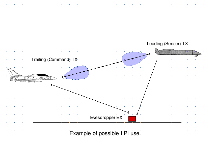
Steganography is an approach which has been well known and used for many centuries. In principle it can have a role in many combat situations. The above shows an example where a strike aircraft might be in communication with a preceding (possibly uncrewed drone) aircraft acting as forward sensor platform. The two may need to communicate, but ensure no enemy agencies on the ground can detect this communication link and give away the presence or probable intent of the aircraft. To a good extent, for high flying craft a directional link and use of a transmission band that is attenuated by the water vapour in the lower atmosphere may well help. But using LPI transmissions also makes sense in this kind of situation.
However during the second half of the 1990s it occurred to me that steganography could be very useful in a specific context. This was when Duncan and I were asked for ideas regarding a possible new form of Combat ID system for the UK and NATO battlefield forces. By then I’d already become interested in ‘semi chaotic’ oscillators, etc, which produced complex output waveforms which spread their output over a wide bandwidth in a way that initially looked like random noise, but actually had a quite specific time-varying pattern. And we were also looking into using two- and three-port mm-wave systems to accurately determine the direction of arrival of a signal, and measure the distance to its source without using radar or any active probing of the source. Putting these techniques together seemed to me to be a novel and potentially very powerful way to tackle the requirements of CID on a battlefield.
Question and Answer. |
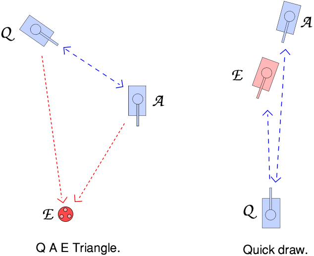
At that time essentially existing CID systems used a “Question and Answer” approach, which can be illustrated by the above diagram. I’ve adopted the common practice of labelling two sides in a conflict as being ‘blue’ and ‘red’. Usually, ‘blue’ is ‘our side’ and ‘red’ the ‘the bad guys’.
The vehicle labelled with a ‘Q’ transmits an interrogation signal ‘questioning’ another vehicle, labelled ‘A’, challenging it to give a response which will identify it as a ‘friend’. If it responds correctly by sending the required response this warns A that Q is actually a friend, and they know not to shoot. Thus the interrogation/response process prevents someone shooting a friend.
In a battlefield environment it is obviously important that this process should take the shortest possible time. Otherwise there is a risk that a potential target which is not a friend may realise that Q is about to fire at them, and be able to shoot first and/or take evasive action! This tends to mean that the Q and I signals tend to of fairly short-duration. Which also tends to mean they need be bursts of high peak power to ensure reliable reception. Alas, this tendency to use short duration, high power signals makes them relatively easy for an eavesdropper ‘E’ to also detect and record. The eavesdropper may not always be able to deduce any ‘key’ relationship between the details of an individual Q and A pair. But simply being able to record some examples may allow them to add warning receivers to their own vehicles, etc. These then can alert the red forces when they are interrogated by a blue force shooting platform, and/or detect when some other vehicle has responded. So such a Q and A process can give valuable information about the blue force to the red force, and they can make use of this later in a conflict.
This is exampled by the arrangement on the right in the above diagram. Here Q sends an interrogation in a direction towards two other vehicles. If, from Q’s viewpoint, the two other vehicles are in almost the same direction then a correct response might be attributed to the ‘wrong’ vehicle, so might not prevent an error. In addition, even if sufficiently different in direction, the red platform may detect both the Q and A of a successful interrogation, and know that the other two vehicles are blue. It can then react accordingly because information gathered by E allows it to do so. Again, a ‘quick draw’ problem can arise, prompted by the use of a traditional Q and A process. There are various scenarios of this kind which may affect the use of standard Q and A systems in a combat environment. Hence although the standard question and answer method is valuable it has some potential drawbacks.
During the 1990s the NATO alliance decided it needed an updated form of CID which might be an improvement on previous systems. As a result, a number of NATO countries decided to carry out some research and put forward individual systems. These were then compared to decide what final system might be preferred. All of the systems which were developed and tested – bar one – used improved technology to get better results using the Q and A method. However the UK decided to develop and propose a novel approach, based upon steganography.
This decision arose out of discussions Duncan Robertson and I had with people at DERA. We realised that it should be possible to put an ‘LPI beacon’ on vehicles whose output would be ‘masked’ by background noise unless you had key information about its behaviour. This made it safe to have it radiate continually. Having this beacon always on, there was also be no need for an active interrogation signal. As a result, a number of the snags of the Q and A process were eliminated. The challenge was, instead, to make a suitable beacon and a detector which those with the key info could use to identify friendly vehicles. So that’s what we set about trying to achieve...
I’ve already outlined the techniques we proposed for the actual LPI beacon. The MM-Wave Group were already skilled in developing mm-wave systems using quasi-optics, so we decided that this should also be the approach we’d employ for building a ‘concept demonstrator’ receiving system. For test purposes this would operate over the frequency region around 90 - 100 GHz. And since the effectiveness of the masking method we’d devised would increase with the frequency range it covered, the aim was to have beacons that could pseudo-randomly spread the transmission over a bandwidth of 1 GHz or more to increase the background noise levels facing an eavesdropper. To put this in perspective, the entire spectrum devoted to AM radio, FM radio, DAB, and terrestrial TV broadcasting in the UK fits into a bandwidth of less than 1 GHz. So it represents quite a wide bandwidth for an eavesdropper to have to search for a low power signal that is moving around in a way they can’t predict!
|
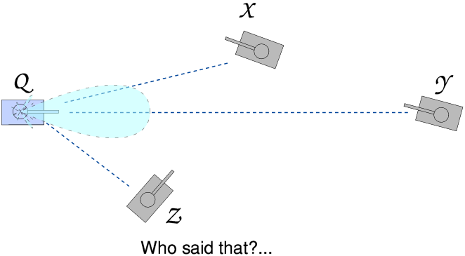
In addition to being able to recover and identify the LPI transmission, the receiver needs to be able to respond only when the source was in a narrow spread of directions that was well defined. This is because there may be a number of potential friends/enemies around and it is vital to know which one of them may be giving a ‘friend’ indication. The difficulty here is that conventional directional antennas of the size likely to be fitted to vehicles tend to be too small to provide a really narrow beam. The above diagram illustrates this problem. Q wishes to check if Y is a friend before shooting at it. However the antenna Q is using has an antenna pattern shown by the light blue shape. It does concentrate in the direction that ‘Q’s gun is aiming at. But it also will radiate towards, and receive from X and Z because, although they are off the main peak of the pattern, they are closer, so the transmission losses due to distance will be less. Hence a ‘friend’ signal from X or Z might be taken as coming from Y! However, by using a 2-Port spatial interferometer we were able to provide much higher directional discrimination than would have been obtainable from a conventional receiver of similar size. Hence as a result we would be able to determine if a signal came from Y rather than X or Z.
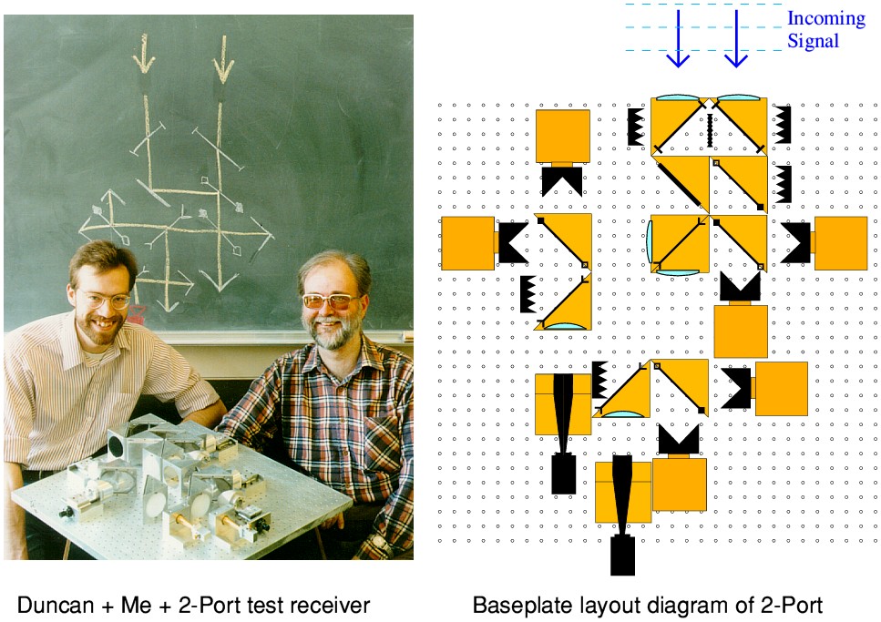
|
The photo to the left of the above illustration shows Duncan and myself sitting beside the original quasi-optical circuit we devised to carry out the task. On the blackboard (greenboard?) behind us we’d chalked a simple circuit diagram of the optical arrangement it employed. The diagram on the right-hand side of the above illustration gives a clearer view of the optical circuit arrangement.
Note this baseplate layout diagram is essentially a view ‘from above’ and the array of small circles represents a set of locating holes in a horizontal baseplate onto which the various circuit items are mounted. Any incoming signal here is assumed to arrive from the top of the diagram, as shown by the blue arrows. This represents the nominal ‘boresight’ direction which the system is looking towards for any signals. However it collects this via the two input lenses, which are spaced a short distance apart. The system is set up such that when the signal arrives from the boresight direction, the two inputs will share the same phase and amplitude. However any slight change in the angle of arrival in the horizontal plane will cause the incoming signal to reach one input slightly earlier than the other. The circuit can detect this by carrying out a process of two-beam interferometry. If the inputs are in phase the two output detectors will share the incoming power equally. But any change in direction of arrival will unbalance this situation and hence can be used to sense that the signal didn’t come from the boresight direction.
|
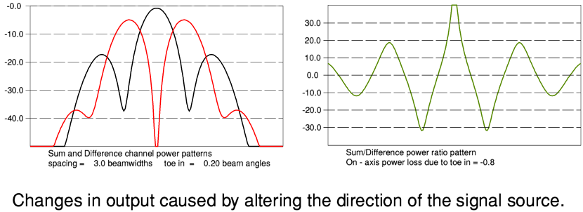
The above graphs illustrate the behaviour of a typical 2-port arrangement of this kind. The black line shows the sum of the powers reaching the two detectors. The red line shows any difference between the levels reaching them. You can see that this difference level exhibits a narrow ‘dip’ near the center of the pattern. The green line shows the result of calculating the sum/difference ratio. This gives us a large peak in the boresight direction which is clearly much narrower than the peak lobe of the black (sum) line. The result is an ability to obtain a much sharper discrimination for the range of directions that will give a reliable ‘friend’ response. Since the process uses the sum as well as the difference, it also tends to suppress the effect of a closer friend’s signal from an off-boresight location nearby giving a false ‘friend’ result when the system is being pointed at a non-friendly vehicle.
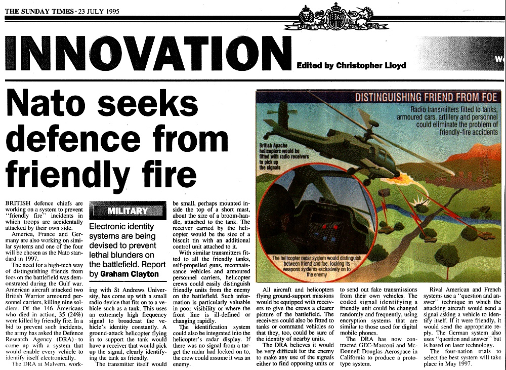
Sunday Times 23 July 1995 |
During 1995 the ‘competition’ for developing a new CID system began to be given press publicity and it became quite a high-profile project. The above shows one of the early press releases which lead to an article in the Sunday Times ‘Innovation’ section that appeared on 23rd July 1995.
We employed a Quasi-Optical system of the above kind for many of our early demonstrations and tests. However we also started working on a 3-port system because we knew that offered the added benefit of being able to make range measurements, and thus help distinguish possible sources which were actually at the same bearing, but different ranges!
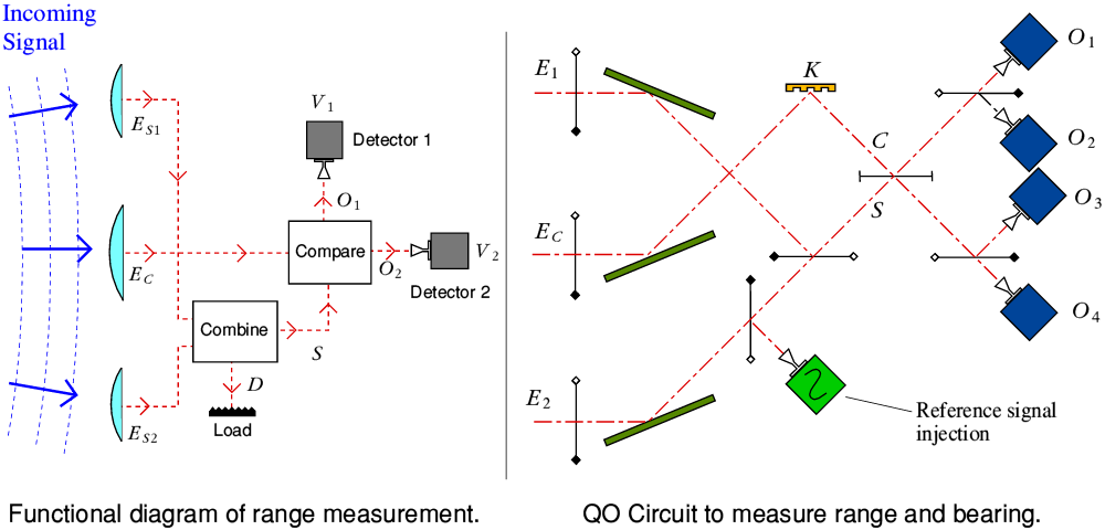
3-Port Diagrams |
The above diagram illustrates how a range measurement can be obtained. The process adds a third input port, located in between the two used to determine the bearing of a signal source. When a signal arrives from a transmitter at a finite range the arriving wavefronts will be curved with their nominal center of curvature located at the point the transmission was made. This slight curvature means the signal arrives earlier at the central port, C, than its average time of arrival at the two outer ports, S1 and S2. Hence if we combine the inputs from S1 and S2 and then phase compare this with the input from C we can determine the curvature, and hence the range to the source. In addition to a functional diagram the above illustration also shows a Quasi-Optical circuit diagram which can simultaneously determine the range and bearing of a signal source by comparing the relative signal levels which reach four output detectors. The device K is a reflecting quarter-wave plate which simplifies the required arrangement, but various other arrangements – and of course other types of electronics, etc – can be employed to perform the same function.
When I arrived at St Andrews in the 1980s one of my first tasks was to develop and run a basic Practical Electronics teaching laboratory course. I’d actually based this on one I’d helped to run at QMC, but had updated and expanded what it covered. By the mid 1990s I’d come to feel that some new teaching material would be helpful and I’d noticed the appearance of ‘multimedia’ systems which could be run on a computer to provide individual students with a way to learn at their own rate. So I’d bought a copy of one of these multimedia development packages and tried using it to create a useful resource for students. Unfortunately, I found that the package had annoying limitations which made it more suitable for primary schools.
At the time the World Wide Web was quite new, and – compared with nowdays – small. Only a low percentage of UK homes had an internet connection. But Universities had fairly quickly set up network access, and by the mid 1990s I was able to use email and newsgroups from my office. So my thoughts turned to using webpages. I then realised that this might let me create a useful teaching resource which people could freely access around the world, not just in the St Andrews Physics building. I found this idea attractive for two reasons. Firstly, that I felt that in effect the UK public were paying my wages, so it would be good if I could provide a free resource anyone in the UK could use without further payment to me, and use it to learn more about electronics, etc. Secondly, I liked the thought that people in other countries might find it useful, particularly in places where colleges teaching electronics were rare. I also guessed that the University might like the idea as a way to ‘advertise’ St Andrews.
The Scots Guide to Electronics. |
I can’t now recall exactly when I started writing my first webpages for what became “The Scots Guide to Electronics”. The earliest archive version I’ve been able to find carries a copyright date of 1995, and is from an archive I made in 1998. However I recall that I added this ‘copyright statement’ some time after the first versions appeared on the web. So the first pages were probably made available a year or so earlier than 1995. (And to be honest, I only put the ‘copyright’ statement on the page because someone else at St Andrews insisted I added it!) Over the next decade I steadily added more material so if you visit it now you will find it includes many more pages and topics than it did in 1995.
From the perspective of 2019 many of those pages now look quaint in layout with relatively small, low resolution, diagrams, etc. However when building the site in the 1990s I was acutely aware that many of the computer systems and network links, particularly in poorer countries or areas, might find it problematic to have to fetch large amounts of data for big detailed illustrations, etc. So I wanted pages that were as ‘resource lite’ as possible to maximise accessibility. For me, content was king, and I wasn’t trying to impress anyone with fancy ‘whizz wheels’ or my skill (sic) in graphic design.
For many years Chris had been a supporter of the movement to abolish apartheid in South Africa. Now that it had ended and Nelson Mendela was free she wanted to visit the country and see how things were there. So on the 1st of March 1996 she flew out to South Africa on a trip organised by the left-wing ‘Progressive Tours’ agency. I was unable to go with her, despite wishing I could. By this time I was prone to serious anxiety attacks which tended to be prompted by having to travel. As with any kind of mental illness the symptoms often make no sense when considered rationally. Sometimes I could travel to ‘familiar’ places. So I was able to make trips to Malvern and elsewhere for a few days at a time when accompanied by someone else I could rely upon. Although the people in my research group at the time had already become aware that this wasn’t always the case, and at times were frustrated by my deciding I was unable to go to a meeting somewhere.
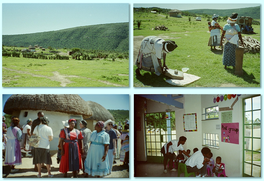
Some photos Chris took in South Africa in 1996. |
Because of this, Chris went with a good friend – Ann Mead – and they spent a couple of weeks touring South Africa. Although remaining at home I was anxious in case she was unwell whilst away, so found it a difficult time. Indeed I was haunted by the fear that she would die whilst away and I’d never see her again. But once she was home again I was very pleased that she had gone despite my not being able to accompany her. During her visit she went to various locations, and the above photos show a small hamlet and a new school. The tour include Soweto where she bought what looked from a distance to be a straw sun-hat, but was in fact made from old pairs of tights, dyed to look colourful. A hat she wore for many years afterwards. For her the highlight was a trip to the South African Parliament to watch and hear Nelson Mendala speak, made magically special because during this he looked up at her and smiled.
To some extent my anxiety was prompted by a process during the late 1990s where Chris increasingly went though ‘down’ periods where she felt unable to see anyone or go out, and became seriously depressed. But although these deeply worried me, it is clear now that my excessive anxiety was also due to my working too hard.
Despite my increasing anxiety, Duncan and I went on a number of short trips as a part of our work on the UK’s CID system. Initial tests and measurements used the Quasi-Optical 2-port receiver at St Andrews, looking out a signal source on what we called the ‘bird table’ up to about a 100 metres away. This established that the technique worked as designed. However we clearly needed to carry out tests at longer ranges. To to this we went to Pershore airfield which was conveniently located near DERA in Malvern. Pershore had one of the longest runways in the UK. We located the 2-port receiver in a sort of caravan with an opening side – a bit like the kind of portable trailer which can be used to serve food and drink at an outdoor event, except that we used the counter to support the receiver system. We put this at one end of the long runway with the receiver looking towards the other end. A CID ‘beacon’ was attached to a landrover and this was then driven up and down the runway. The results confirmed that the system would operate at the expected ranges and gave the level of directional discrimination we required.
The group had also taken on another postgraduate student, Peter May, funded by DERA to help us. My main interest was in developing the UK CID system. Duncan worked with me on this, but he also worked with Peter on a more general task. This was to assess the vulnerability and detectability of all the candidate systems. Hence although Peter was my research student at the time his work concentrated on a different set of problems. One issue which particularly interested me in terms of detectability was that I’d realised that the way conventional frequency hopping was performed gave the signal some characteristics that helped an eavesdropper detect the existence of the hopped signal. This had implications for the use of a frequency modulation system which employed a DAC (digital to analogue convertor) and a digital sequence of values to modulate the transmissions. In particular, using a set of specific ‘hop slots’ and changing slot at regular interval could be a weakness.
The concept testing system we developed allowed us to establish that a 2-port receiver could deliver the required behaviour. However our quasi-optical system wasn’t in any way ‘battle hardened’ or in a physical form suitable for use on a tank! A part of the GEC organisation was given the task of producing a form of prototype receiver and beacon which would be suitable for use in a real military combat situation. For the sake of rugged reliability, their system was physically very different, but essentially functioned in the same way as our QO one. So once they had produced a prototype we switched to assessing the UK CID system using that.
The GEC version of the 2-port UK CID receiver. |
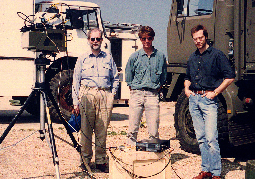
The photo above was taken at the Lulworth testing range with – left-to-right – me, Jonathan Borrill (DERA), and Duncan. The GEC receiver is on the tripod. As shown, the left-hand side of the GEC box can be seen to be white rather than Army green. This is because it was made of a material that is transparent at mm-wave frequencies. So far as I can recall, I only attended one set of tests. The others were done by Duncan with Jonathan and/or Peter May. Jonathan was doing his famous ‘top gun’ impersonation for the photo...
Tests established that the GEC version also worked as expected. As with all engineering prototypes it also showed some bugs during testing and thus enabled them to be fixed before any production versions might be made. However for some reason, despite raising the point at many meetings, I could never get them to actual fit a filter of the kind which was needed to prevent the weakness which concerned me about conventional hopping. Instead they built a system with a couple of external signal sockets on its case. As produced by GEC these were simply connected together using a short coax. The idea, I assume, being that someone else could add the required filter if they wished. In the end this became a source of a running joke between us because fitting a suitable filter would be trivially easy!
At the end of March 1996 I received a letter telling me my second application for promotion had been turned down. As the previous year it gave no clear reasons. So I wrote again to request a clear explanation. The response was along the lines of, “You’re doing the right things, but no cigar”. I wasn’t satisfied by this and explained why in another letter to the professor overseeing the process. Put bluntly, on all the factors specified as the official basis for assessment my track record was demonstrably better than most of those who had been promoted! What was becoming clear, though, that – although no-one would admit it – some kinds of ‘output’ were regarded as being ‘better’ than others.
Most academics at the time were funded almost entirely via the UK Government ‘Research Councils’ and the grants they issued. However a large fraction of the MM-Wave Group’s funding came from other sources – industry, defence establishments, etc. Similarly, although I’d published more than others, the results went into a much wider range of journals, magazines, books, etc, than was the norm for most academics. So although the MM-Wave Group brought in a high level of funding to the University, and raised its profile in many places, it looked like it wasn’t ‘academic enough’ even though none of the stated requirements, nor anyone I spoke to officially, were willing to say so. This annoyed me not only because it seemed to downgrade my own work, but that done by others in the group. In effect the University attitude seemed to be “Thanks for the money and the profile, but although we won’t admit it, we’re holding our noses in distaste because of the way you’re succeeding”. This also reminded me of earlier in my career when an attempt had been made to extent my probation without any justification and against the established rules. I therefore determined to apply again, and make my next application one they’d find it difficult to reject!
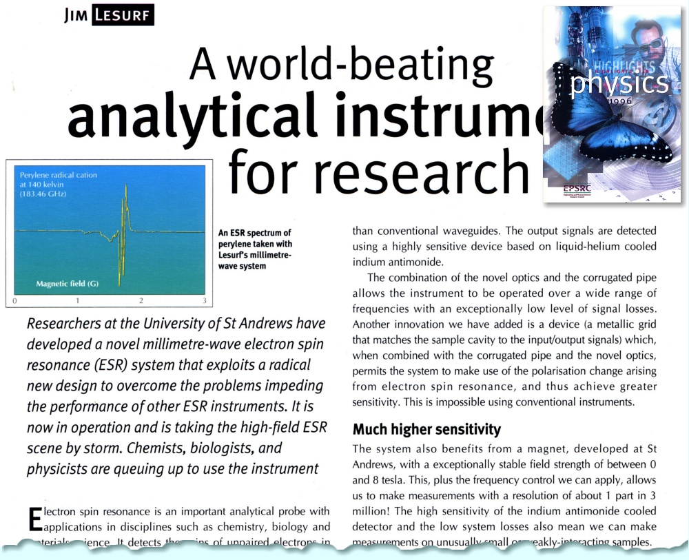
Highlights in Physics. |
I’d been invited to write a short item on the ‘TopSpin’ ESR system Graham Smith had developed in conjunction with Prof Peter Riedi and myself. This was to appear in the SERC publication ‘Highlights in Physics 1996”. I was delighted for this to be published as an outstanding project by the SERC themselves, but when I saw the final version I was also embarrassed by one detail the editors had added without my knowing. I was happy to write the item and be identified as its author. But a comment on one illustration said: “An ESR spectrum... taken with Lesurf’s millimetre-wave system”. I assume this was added because I’d written the article, but it should have made clear that the actual instrument was mainly the work of Graham and Peter! OK, at that point Graham wasn’t a lecturer, so not permanent staff. But Peter and I had been lobbying for him to get a lectureship at St Andrews and it had already been obvious for years that he deserved a permanent post. Nevertheless, the way this article and comment appeared under an SERC imprint did rather contrast with the odd attitude of the relevant University committee toward my own applications for promotion...
During the 26th to 28th of June 1996 The official NATO working group on CID held a full meeting at St Andrews. This gave them a chance to see for themselves our work on the 2-port system, and have a look at our receiver in operation. The sessions were held in ‘closed’ meetings at New Hall which Duncan and I attended, and I gave a presentation on our work and the results we had obtained up to that point. I was told by both Duncan and the Chairman of the session that “jaws dropped” when I showed some of our results which established the level of bearing discrimination, etc, we could achieve using the concept demonstrator. There was also an organised ‘dinner’ for the working group. Both haggis and Scottish beef were on the menu. Despite this being the period when ‘mad cow’ disease was scaring people we ate the meals and thoroughly enjoyed them. So overall the meeting went very well.
A number of changes were made to Chris’s medication during the latter part of 1996 and during the following years. The nature of her fits had started to change. In the past they’d almost always just been an ‘absence’ followed by some minutes of being confused, then going into an ‘automatic’ phase where she was able to do things like get home safely. But there was an increasing tendency for her to become very frightened and confused, not knowing where she was, etc. For example, on one occasion when we were in Dundee supermarket she started shouting that she was terrified, shaking, and trembling. This generated rather pointed attention on me from the shop staff because they understandably suspected I was attacking her in some way! But by simply talking to her quietly and acting gently I was able to calm her down and satisfy onlookers that I wasn’t up to no good. It must have been more alarming for people when I wasn’t there to explain what was happening and take care of her. There was also a general increase in the number and severity of her fits.
Despite this, most of the time she continued to be very active, and refused to let the fits stop her doing what she wished to do. In a typical week she might go to two FHC-related meetings in locations like Glenrothes, Kirkaldy, or Cupar, and do a couple of half-day sessions at the CAB. This, of course, in addition to our going out, shopping, etc. And of course she couldn’t drive because of her epilepsy, so the travel was by public transport. Because of the fits, one result being often losing gloves or pairs of glasses on a bus, etc. Unfortunately these periods alternated with bursts of a few days when she felt unwell, and too nervous or anxious to go out or see anyone. At those times she increasingly took to spending time in bed, and not always getting up to eat meals. No medication she’d tried had ever either been able to stop her having any fits, nor help with the periods of withdrawal and feeling unwell. As a result she continued to be willing to experiment with changes to her medication in the hope that it might help her, or others. So during the latter part of 1996 and in later years she often had her medication changed. Alas, this generally led to new side-effects or problems, not a general improvement. Fortunately, most of the time she was active and busy. This was the Chris people saw as she helped others, and she enjoyed doing so.
By the start of 1997 the overall area of my academic/research work had expanded to the point that I had nine other people working with me on various topics. However the bulk of my time was devoted to the MoD/NATO-related ‘battlefield’ area of research. The CID work was shifting away from the Quasi-Optical concept demonstrator that Duncan and I had developed and tested. The battle hardened prototype developed by GEC was taking its place, and used on test ranges, etc, to evaluate it performance in conjunction with real front-line vehicles. From an academic point of view I felt that the concept was now established and I began to spend more time on considering the 3-port technique to provide passive ranging as an alternative to conventional radar. This grew out of a request by DERA that I look into ways to transmit signals that had a low probability of intercept or ‘LPI’. i.e. which an enemy would find hard to detect or exploit
Radar is a well-established and widely used technique. However it does have one key weakness which is inherent it the way it works. In order to determine the location of an object it – as with conventional CID – has to be ‘illuminated’ (sometimes also called ‘painted’) by a deliberate transmission. This then causes a reflection which can be detected to help locate the object. However the situation is worse than for CID because the return from a ‘friend’ who gets a CID ‘interrogation’ is an appropriate active ‘response’. Whereas radar has to depend on a small fraction of the radar signal’s power being reflected and returned to be detected.
The power levels suffer the usual ‘inverse square of the range’ reduction on both the outward and return journeys. So, taking round numbers for the sake of example, if we had a radar that fires out a 1 MW pulse, we might find that only a millionth of this hits a target object and is scattered by it. i.e. 1 Watt is scattered by the target. That reflected power also then spreads and there is another factor of a million lost before the radar picks up the result. Thus the radar sends 1MW, the target gets presented with 1 Watt, and the return captured by the radar is only 1 micro-Watt! To make this worse, double the range, and the power getting back from the target would only be one sixteenth of a micro-Watt when a radar warning receiver (RWR) on the target would still get 250 milliwatts!
This makes it relatively easy for cleverly made RWR on a potential target to detect radar signals long before it gets close enough for the radar operators to detect the reflected return. It can then either dodge the radar, or launch a specialised ‘fly down the radar beam’ missile to dispose of the radar long before it can even see the target! Hence the concept of trying to find suitable ‘LPI’ radar signals that would elude being so easily detected by a target’s RWR. This can be done in various ways. The best known example being the principle behind a system the USA proposed called ‘Silent Sentry’ which uses the civilian VHF/UHF broadcasts in an area as the transmitters, and simply looks to see if these are being reflected from aircraft. Thus locating them without actually using a special-purpose radar transmitter.
In a battlefield context, consideration of LPI had set me wondering about using spatial interferometry to determine the range as well as the bearing of an object. This might make use of either deliberate transmissions produced by a target, or simply the thermal emissions from it being different to those of its surroundings. Given that the UK CID system used a steganographic approach the same beacons could, whilst being LPI, potentially be used to provide the locations of friendly vehicles even when in the same direction as hostile ones. Thus making the UK CID technique more useful. In this situation the signals were ‘one way’ so avoided the ‘two way’ loss scaling problems of conventional radar. With these possibilities in mind, Duncan and I spent some time developing and testing a 3-port concept demonstrator for LPI ‘passive ranging’.
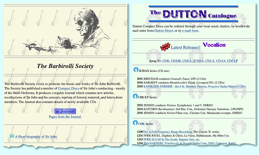
Barbirolli Society and Dutton CDs. |
During 1996 I arranged to have an internet connection at home as well as in my office in the Physics building. This was very useful in allowing me to work at home and avoid distractions when writing and doing various calculations, etc. I’d recently joined The Barbirolli Society (JBS) which had gone though an almost dormant phase. Having started building the ‘Scots Guide to Electronics’ webpages it occurred to me that the JBS might well benefit from having some webpages to let people know they existed, welcomed new members, and were now providing CDs of music conducted by Barbirolli. So I exchanged some emails with the Society and started putting up some web pages for them in my home webspace. Mike Dutton was remastering and transferring old recordings onto Audio CD for the JBS, and since I was mentioning the details of these on the Barbirolli pages, one thing lead to another... and I also started producing some webpages for Dutton as well. The above shows some screen grabs of early versions of these webpages which appeared in 1997. By modern standards, not particularly fancy. But they did the job and helped raise the profile of the Barbirolli Society and the CDs becoming available. Over the next decade or so I continued to build these sites as a ‘hobby’ interest out of love for the music, alongside continuing to add material to the ‘Scots Guide’.
During February we did some initial ranging measurements using a 3-port system looking out of the mm-wave laboratory window at a low-power transmitter set at locations 50 to 100 metres away. These confirmed that the technique worked. But it wasn’t possible to get much further because the view was obstructed by other objects. So for longer ranges we needed a better location. Duncan and I were also very busy with NATO visitors coming to see the work we were doing during this period. I particularly recall one week at the end of February when we had to show what we were doing to five groups of visitors, some of whom wanted to spend more than one day with us during the 5-day working week! Fortunately, they all seemed very impressed.
February was also memorable for a train journey that essentially went though a lake! Duncan and I made a visit to Lancaster University to discuss the possibility of our working together to develop a mm-wave scanner for use by vulcanologists. We travelled down to Lancaster by train. At the time there was a great deal of very heavy rainfall. As a result, a long stretch of railway track across Shap was under water! This was deep enough to submerge the wheels of the InterCity train we were in. The driver was only able to move at a pace that was slower than you could have walked – if it had been dry! They worry was that the track may have been washed away, or would fail under the load, causing the train to derail or topple over! We apparently came close to having to be evacuated from the train and rescued from the moor during the rainstorms. But fortunately the train managed to eventually get us to Lancaster, albeit some hours later than scheduled. So it was an interesting trip for more reasons than one...
During March 1997 I was informally told that my latest application for promotion to a Readership had been accepted. I got an official letter confirming this on the 3rd of April. I emailed the people who’d acted as my referees and let them know that at last it had been established that I could read! I’d only actually wanted the promotion because it had seemed increasingly odd not to be a Reader (or Professor) given the sheer scale of the mm-wave group’s activity. Having the title would aid us in getting future grants and contracts. The said, the first result was that we organised a mm-wave group celebration dinner held at our favourite restaurant in town, the Vine Leaf, and we had an enjoyable evening.
Unfortunately, the news didn’t make me as happy at the time as I’d have liked as other events weren’t so pleasing. Chris had been taking some ‘experimental’ anti-epilepsy medications as part of a trial run by the Dundee Royal Infirmary (DRI) under the supervision of her consultant there. The medication gave her unwanted side-effects, etc. So she stopped taking it at the end of March. She then experienced a particularly upsetting rise in the number of fits, and their severity. During the first days of April she had two very bad major fits and a number of smaller ones in bursts – up to five in one day!
Just to make things even more ‘interesting’ we were also having a new bathroom installed at home and this was proving rather disrupting. When I emailed Professor Mike Kelly who’d been one of my promotion referees I described it as “having a bathroom fitted sideways” to indicate the level of disruption it was causing. Side effects included the central heating and hot water system ceasing to work correcting until the plumber returned and ‘adjusted’ some of the pipe runs they’d altered when installing the new bath. This was because they’d moved the pipes so that some tilted against the gravity flow required for the boiler to heat up the water in the hot water tank. Overall, it made me realise just how weird the heating system arrangements are in many homes in the UK, and why they baffle or amuse people from other countries.
In April 1997 I received a letter from Kathryn Cantley at the Institute of Physics (IoP) letting me know that my book on Information and Measurement was proving to be a ‘best seller’ and had won an “outstanding textbook award” from the USA. As a result, stocks were running out! She proposed that we issue a second edition in paperback. This was very welcome news as I’d deliberately aimed the book at undergraduates rather than lecturers and wanted to make it a good way for people to find their way into the topic, bypassing some of the mathematical bafflegab that got replicated from one old textbook to another. So I agreed, and also arranged to update one chapter and add further material, despite the paperback edition being cheaper. Which I looked forwards to doing, but did of course mean yet more work...
During April, Duncan Robertson and Peter May went on a trip to Germany. This was arranged to enable them to carry out ‘vulnerability’ checks on the various CID systems being compared on a test range. For my part I largely left that area to them and mainly confined my involvement to some discussions over their test methods and analysis. This was because my own main interest was now on the 3-port passive ranging idea and using the concept demonstrator Duncan and I had assembled. The task Duncan and Peter were asked to carry out was to put together ‘COTS’ receiver systems which might be able to easily detect and locate (at least in bearing) the emissions from the various CID systems. Here ‘COTS’ means Commercial Off The Shelf. i.e. the system they used had to be built from electronics anyone with the cash could buy ‘off the shelf’ as standard equipment. Hence items a potential enemy could also quickly assemble given the money and someone smart enough to buy the items and use them appropriately. The outcome made clear that – as we’d expected – the conventional CID systems under test were easily detectable because the signal powers they used were so high and their patterns un-natural. In this respect they weren’t very different to the CID systems already in use at the time.
Starting in May 1997 and continuing over the summer we began using the 3-port system with it looking out of a top-floor window of the Physics building.
3 Port Demonstration/Test receiver looking out of a teaching lab. window in the St Andrews Physics Dept. |
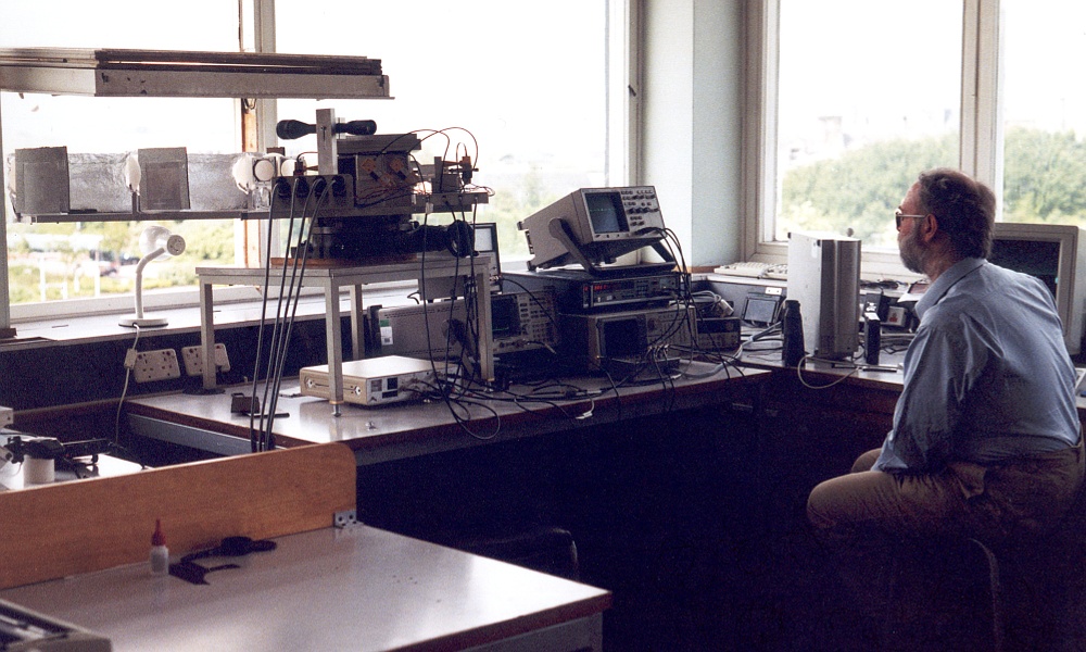
The above photo shows the 3-port concept demonstrator system looking out the window with me gazing at oscilloscope screens to see signs of it receiving signals from a transmitter. During the summer months we made range measurements using a low power transmitter over distances out to about 2 kilometres.

Close-up of 3-Port system. |
The above shows a more detailed view of the 3-port front-end. This was assembled using our by-then standard method for ‘breadboarding’ mm-wave quasi-optical arrangements, but with some extension rods holding the collecting lenses. The rods didn’t really hold the lenses as rigidly in place as we would have wished, but were sufficient to show that the 3-port interferometry process was capable of providing accurate range measurements at usefully long ranges.

The 3-port test transmitter. Viewed from the Physics Dept. window. |
The above shows a view out of the top floor window. This overlooked the school sports fields across the road, and beyond those, the golf course. I’ve identified the transmitter in the main image with a red arrow and ‘TX’ label. The inserted image shows a close-up of the transmitter. Alongside the mm-wave transmitter (‘beacon’) we also mounted a laser retro-reflector and used a standard surveying laser to check the range for comparison with our 3-port measurements.
For obvious reasons we need an alert but amazingly patient and long-sufferring body to operate the beacon and ensure it was working, trundle it around, etc. So we enticed an innocent undergraduate – Paul Cruickshank – to take on the task as a ‘summer project’. Projects of this kind tended to be offered to undergraduates who had shown signs that they’d be likely to gain a good degree and then become valuable as a research student. Paul had clearly entered this category by the end of his second year as an undergrad, and accepted the project. As a result he became a vital member of the team over the summer.
In the process he also endured bad weather, tedium, and sports field groundsmen who shouted at him for pushing his ‘contraption’ across their nicely top-dressed grass! We used a walkie-talkie to communicate with him when we wanted the beacon to be moved. He discovered that when at long range he had to hold his walkie-talkie above his head for it to be able to communicate with us. So in practice our mm-wave beacon and 3-port worked better at long range than the commercial walkie-talkie. (N.B. In those ancient days before modern mobile phones, tablets, etc, a dedicated ‘walkie-talkie’ was the kind of portable two-way radio needed to communicate with someone out in a field unless we waved flags!) Fortunately, this didn’t cause him to decide research was a PITA and after he graduated he became a research student under Graham’s supervision. Hence establishing he was, indeed, as mad as the rest of us!
New Scientist ‘Technology’ section 28th June 1997. |
At the start of June I was phoned by one of the journalists at New Scientist and he asked me some questions about the CID project. I was well-known at New Scientist by this time because I’d written a number of articles for them, and also often helped them make sense of technical items which fell outside their experience. I was only able to give him some general comments because the details weren’t publishable or reportable. A report then appeared in the issue cover dated 28th June 1997. This prompted my getting a call from DERA who hadn’t ‘cleared’ the item in advance. However I explained that I’d only said what had already been made public and that I’d been phoned out of the blue, so it was agreed that I’d behaved correctly.
There was another NATO meeting at St Andrews on the CID project at the end of June and start of July. In addition to being able to update people on progress with the UK CID system this gave us a chance to show them the 3-port ranging demonstrator and the success we’d had in making useful range measurements. Thus proving that the idea worked as it should. I particularly remember showing various ‘big hats’ the system as it made range measurement on the beacon Paul was operating in the distance. This was because each time it obtained a new range value the I’d programmed the controlling computer (Acorn, of course!) to produce a ‘bong!’ noise. And when I pressed the ‘s’ button on the computer keyboard it would generate another noise to confirm it was flushing the data buffer and storing the most recent measurements in a file. However this sounded the noise of flushing a toilet to confirm the action. Duncan had suggested it might be wise to change this particular sound effect before the NATO demo, but I, of course, forgot... So we had to endure being flushed with success.
During July Chris wrote to her then-GP about the rise in her feelings of anxiety, panic, confusion, and worsening memory problems, all combined with her having more fits than in previous years, and more of them being serious major fits with convulsions, etc. But despite seeing her GP and epilepsy consultant quite often during this period, her condition continued to deteriorate. However whenever she could, she continued to go to FHC meetings and work for the CAB. Over the summer I had offered a research studentship to an undergraduate who had seemed quite promising. However although he’d said he accepted and we’d sent the relevant forms to him, they hadn’t been filled out and returned. I repeatedly tried to contact him as the deadline for the studentship was approaching. Although I spoke to his mother and his sister and he promised them he’d send the forms, they never appeared. As a result I decided we should offer the studentship to another excellent candidate. The snag was that this meant we needed evidence to show the initial one wasn’t now accepting the offer, which was difficult because I could never get in contact with him.
However in mid-August Peter May (who was a sub-warden at the Hall of Residence) tried the potential research student’s room and found that he’d vacated it, taking all his things away without telling anyone. All that remained were a few items including a copy of my mm-wave book. Having established this, the head of the Physics Department agreed with me that it was now safe to offer the studentship to someone else. So having already spoken to him about it, I offered the position to Duncan Pryde who accepted and joined the group at the start of the new academic year. Now we had two people in the group called Duncan, and they quickly became distinguished by Duncan Robertson being ‘big Dunc’ and Duncan Pryde being ‘little Dunc’.
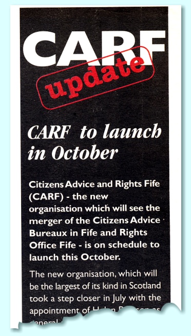 In September 1997 the ‘Fifer’ magazine (a free publicity sheet produced by the Council) announced that in October the Council would combine the Fife Rights Office and Citizens Advice Bureaux into a single organisation. It would be the Council funded and controlled organisation: Citizens Advice and Rights Fife (CARF).
The Council spun this as a sensible merger which everyone was welcoming. However the reality was that almost all the CAB volunteers and staff opposed the ending of an independent CAB service in Fife. The change made Fife the only council area in the UK that lacked an independent CAB. Chris and others had campaigned against the change, as had local GPs, and thousands of members of the public. Even the local MEP, Alex Falconer, opposed the ‘merger’ despite being a Labour Party MEP and hence in the same party as those running Fife Regional Council at the time.
The big concern was that people who had problems caused by Fife Council would be reluctant to seek help from an organisation that would be seen to be ‘in the pocket’ of the Council they wanted to complain about and ask for help to fight!
In personal terms this was a serious disappointment for Chris because working at the CAB had for many years given her a role helping others. She had really enjoyed doing this. It also helped her cope with the frustration that she’d been unable to find any employer who’d give her a job, despite her qualifications and experience, because of the general fear of epilepsy. The closure of the CAB also meant the group of volunteers who had enjoyed working together to help people was breaking up because they refused to join CARF. During September Chris and the other workers at the St Andrews CAB had a collection to buy farewell presents for its two paid managers, and a farewell party was held on the 25th. Chris continued to do work for the Fife Health Council, however.
Towards the end of November we were told that our first research grant joint-proposal with Lancaster University to build a mm-wave scanner for vulcanology had been rejected by the relevant committee. This was a real disappointment, particularly for Duncan. Apparently the committee liked the idea in principle, but did not think the instrument would provide a high enough spatial resolution. We didn’t agree with this and immediately began putting together an improved proposal for the next round of submissions. Chris continued to have a high number of fits. For example, during just four days that November she had a dozen fits. These were upsetting both because they caused her to feel confused, forgetful, etc, but also because they made it harder to carry out the kind of work she was keen to perform for the FHC.
In December I went to Glasgow University with Duncan Robertson to present an invited talk. I also discovered that the December/‘Christmas’ issue of “Classic CD” magazine included a mention of my website for the Dutton Labs CD label, along with showing a screengrab of its main webpage! Given the positive feedback I’d been getting for my Information and Measurement book, and the Scots Guide to Electronics this was quite pleasing. And on the 10th we held the group’s Christmas dinner at The Scores Hotel with Duncan Pryde also in attendance for the first time. It rounded off a particularly busy and eventful year.
Jim Lesurf
13,400 Words
29th August 2019